A booster pump with a pressure tank uses the tank to absorb small draws and reduce cycling. The diagram must show where the tank connects relative to the pump, check valve and pressure control.
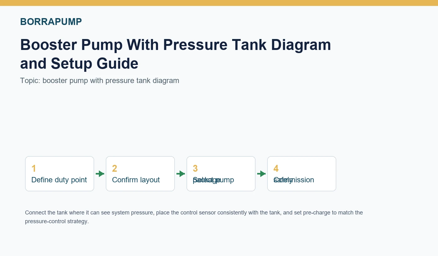
Quick answer: Connect the tank where it can see system pressure, place the control sensor consistently with the tank, and set pre-charge to match the pressure-control strategy.
Selection snapshot
| Primary intent | pressure tank diagram, check valve placement, short cycling prevention |
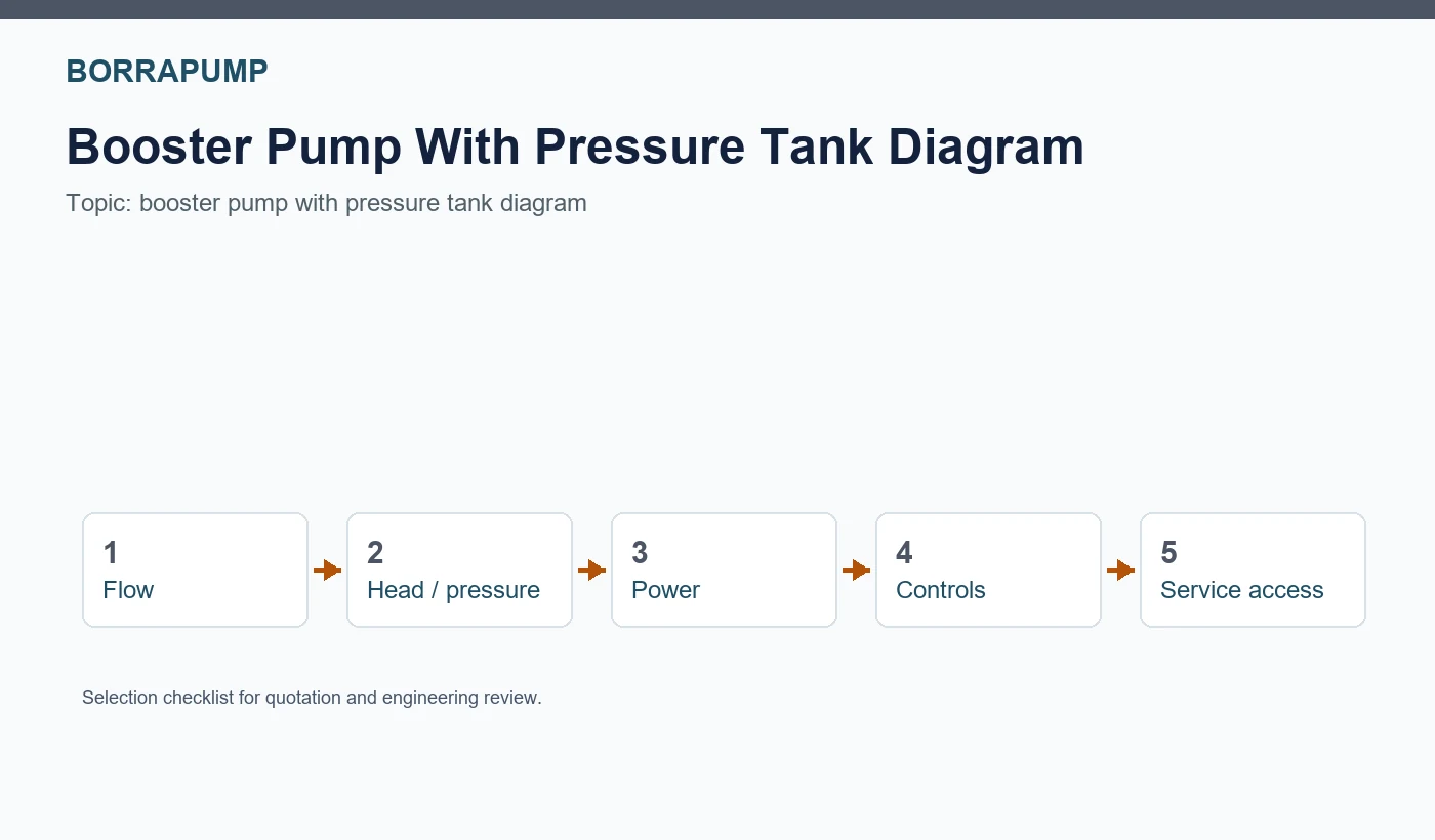
| Main selection inputs | flow, pressure/head, source condition, power, controls, service access |
| Borra fit | Booster Regulator Water Supply Equipment, CDL(F) Vertical Multistage Jockey Pump |
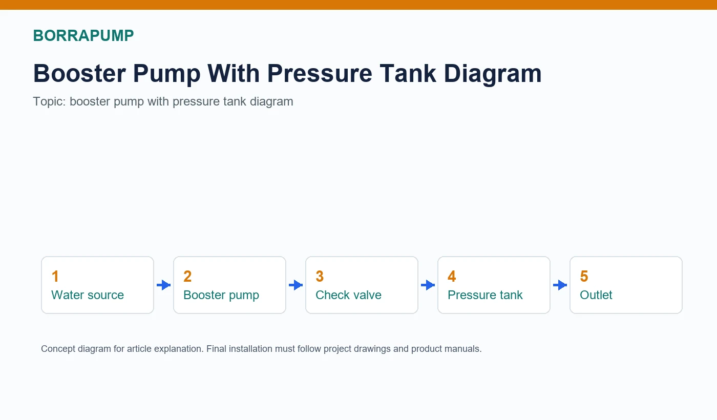
Typical layout
A common layout is inlet source, suction isolation, pump, discharge check valve, tank tee or tank branch, pressure gauge or sensor, discharge valve and building line. The exact order can change by manufacturer and project design.
Tank pre-charge and controls
The tank pre-charge should match the selected pressure switch or control strategy. A wrong pre-charge can cause short cycling, poor drawdown and unstable outlet pressure.
| Primary intent | pressure tank diagram, check valve placement, short cycling prevention |
| Main selection inputs | flow, pressure/head, source condition, power, controls, service access |
| Borra fit | Booster Regulator Water Supply Equipment, CDL(F) Vertical Multistage Jockey Pump |
Common mistakes
Frequent mistakes include placing the pressure sensor away from the tank connection, omitting service valves, using an undersized tank, ignoring suction pressure and treating a simple diagram as a finished installation drawing.
Practical tips
- Show the tank tee and sensor position on the same diagram.
- Record pre-charge and pressure setting during commissioning.
- Use a small tank even in VFD systems if the manufacturer recommends it for stability.
Common mistakes to avoid
- Do not overpressure the tank. Follow tank rating and local plumbing rules.
- Do not set pre-charge without isolating and depressurizing the tank as required by the tank manual.
Related Borra options
For a project quotation, send the flow, pressure/head, power supply, medium, duty cycle and installation conditions. Relevant Borra starting points include:
FAQ
Where does the pressure tank go with a booster pump?
It is commonly connected on the discharge side near the pressure-control point so it can respond to system pressure.
Does the check valve go before the pressure tank?
Often the discharge check valve is before the tank branch so reverse flow does not pass back through the pump.
What is a tank tee?
A tank tee is a fitting used to connect the pressure tank, gauge, switch or sensor, drain and piping in a compact arrangement.
Why does the booster pump short cycle?
Short cycling often comes from incorrect pre-charge, small tank volume, leaks, narrow pressure settings or demand below minimum stable flow.
Can a booster pump run without a pressure tank?
Some constant-pressure systems can, but many projects still use a tank for stability and to reduce starts.
What should be shown in a pressure tank diagram?
Show pump, check valve, tank connection, pressure control, valves, gauge, inlet/outlet direction and service points.