A booster pump diagram shows how a booster pump connects in a water system — the flow path from supply to outlet and the parts that control and protect it. Two kinds are common: a system (installation) schematic showing the piping and components, and a parts/exploded diagram showing the pump’s internal components.
This guide explains what each diagram shows, the system layout, the main parts, and the basics of wiring and controls. For the concept first, see what a booster pump is and the booster pump guide.
Part 1. What does a booster pump diagram show?
A booster pump diagram uses labels, symbols and arrows to show two things: the water flow path and the components that sit along it. Flow is shown with arrows; electrical connections are shown as lines and symbols.
| Diagram type | What it shows | Use it for |
|---|---|---|
| System / installation schematic | Piping path + components (valves, tank, gauges, controls) | Planning and installing the system |
| Parts / exploded diagram | Internal parts (motor, impeller, casing, seals) | Service and ordering spare parts |
Part 2. Booster pump system diagram
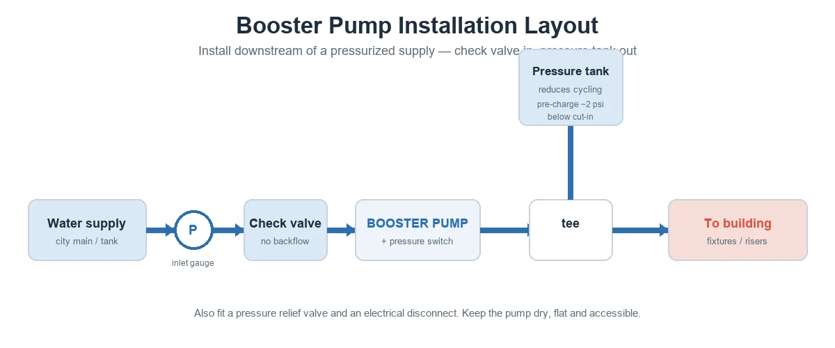
In a typical system schematic the water moves in this order:
- Pressurized supply — city main, tank, or gravity feed.
- Inlet pressure gauge — shows available supply pressure.
- Check valve — prevents backflow when the pump stops.
- Booster pump + pressure/flow switch — raises pressure; the switch starts and stops the pump on demand.
- Pressure tank — teed into the outlet to reduce cycling and steady pressure.
- Pressure relief valve + outlet — protects against overpressure, then feeds the building.
The diagram above shows this layout. For step-by-step fitting, see booster pump installation.
Tip: On any system diagram, confirm the check valve is on the inlet and the pressure tank is on the outlet — swapping them is a common error.
Part 3. Parts of a booster pump
A parts diagram breaks the pump into its main components:
| Part | Role |
|---|---|
| Electric motor | Drives the impeller |
| Impeller | Adds velocity to the water |
| Casing (volute / diffuser) | Converts velocity into pressure |
| Pressure / flow switch | Starts and stops the pump on demand |
| Check valve | Prevents backflow (system side) |
| Pressure tank | Reduces cycling, stabilizes pressure (system side) |
| Inlet gauge & relief valve | Show inlet pressure; protect against overpressure |
Multistage pumps stack several impellers and casings to build higher pressure; their parts diagram shows the staged chambers in series.
A parts diagram also names the wear parts that matter for service: the mechanical seal, O-rings, bearings and wear rings. Naming them on the diagram makes it faster to order the right spares and to plan maintenance without guesswork.
Part 4. How water flows through the pump
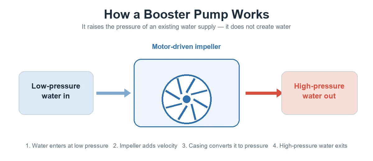
Inside the pump, low-pressure water enters the inlet, the spinning impeller adds energy and velocity, and the casing converts that velocity into pressure before the water leaves the outlet. Many systems add a variable-speed (VFD) drive so the pump holds a constant set pressure as demand changes. See how a booster pump works for the full explanation.
Part 5. Wiring and controls
On the electrical side, a pressure switch or flow switch tells the pump when to run: it senses pressure drop or flow and starts the pump, then stops it when demand ends. Larger systems use a control panel and, for multi-pump sets, a controller that stages pumps and runs them at variable speed.
- Pressure / flow switch — demand sensing.
- Control panel / VFD controller — staging and speed control on larger sets.
- Electrical disconnect — safe isolation for service.
Tip: Keep the as-built diagram with the O&M file and mark any field changes (set pressure, valve positions). Service techs rely on it to order spares and isolate the right pump.
Important: Wiring must follow the pump’s IOM and local electrical code, and should be done by a licensed electrician. Use the manufacturer’s wiring diagram for the exact terminals and protection — generic diagrams are for understanding only.
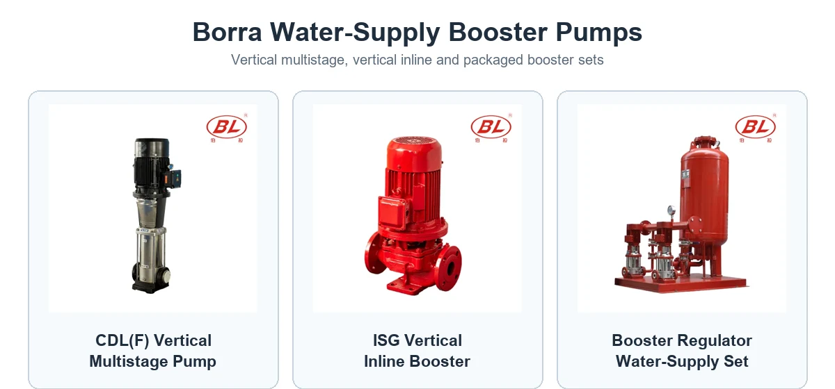
Borra supplies booster pumps and packaged sets with the controls shown above — the CDL(F) multistage pump, the ISG inline booster, and packaged booster equipment.
Part 6. Duplex and multi-pump booster diagrams
Larger buildings use duplex or multiplex booster sets — two or more pumps on a common inlet and outlet header, staged by one controller. The diagram shows the shared headers, each pump with its own isolation valves and check valve, and a single control panel.
- Lead/lag staging: the controller starts pumps in sequence as demand rises and rotates duty to even out wear.
- Variable speed: pumps modulate to hold a constant set pressure, which saves energy at part load.
- Redundancy: one pump can be isolated and serviced while the others keep the system running.
This is the standard arrangement for high-rise and constant-pressure water supply; manufacturer schematics such as the Grundfos Hydro MPC duplex detail show the headers, valves and controller in one drawing.
Tip: On a duplex diagram, check that every pump has its own check valve and isolation valves — that is what lets you service one pump without shutting the building down.
FAQ
What is included in a booster pump diagram?
A system diagram shows the supply, inlet gauge, check valve, pump and switch, pressure tank, relief valve and outlet, with arrows for flow. A parts diagram shows the motor, impeller, casing and seals.
Where is the check valve in the diagram?
On the inlet side, before the pump, so it stops water flowing backward when the pump stops.
Where does the pressure tank connect?
On the outlet side, teed into the discharge line, to reduce rapid cycling and steady the pressure.
What controls the pump in the diagram?
A pressure or flow switch starts the pump on demand and stops it when flow ends; larger sets use a control panel or VFD controller.
Is a single-stage diagram different from a multistage one?
The system layout is the same; the parts diagram differs — a multistage pump shows several impellers and casings in series to build higher pressure.
Can I wire a booster pump from a generic diagram?
Use it only to understand the system. For actual wiring, follow the manufacturer’s diagram and local code, and use a licensed electrician.
What is a duplex booster pump diagram?
It shows two pumps sharing a common inlet and outlet header with one controller, each pump having its own check and isolation valves, so the set can stage pumps and keep running during service.
Why do high-rise systems use multiple pumps?
For redundancy and efficiency: pumps stage on as demand rises and modulate speed to hold pressure, and one pump can be serviced while others maintain supply.
References
- Dultmeier — installation guide & wiring diagrams
- Pressure booster IOM
- Grundfos — Hydro MPC duplex booster detail & schematic
- Hydraulic Institute — pump standards and terminology
Need a system schematic for a project? Share your flow, head and layout and Borra’s team can recommend the right booster set and configuration.