
A centrifugal pump coupling guard prevents access to the rotating connection between a separately mounted pump and its driver. A replacement must cover the actual rotating envelope, stay securely attached, and allow the approved maintenance process without creating another hazard. Selecting one by appearance or motor power alone is unreliable. Start with the pump-set drawing, coupling dimensions, access conditions and applicable guarding requirements, then have the responsible safety and equipment specialists approve the arrangement. This guide explains a replacement specification and acceptance process; it does not provide a universal guard dimension or certify a particular installation.
Identify what the guard must protect
First establish whether the set has an accessible shaft coupling. A close-coupled arrangement may have a different enclosure and access problem from a separately coupled pump and motor. Do not copy a horizontal set’s guard onto an inline unit simply because their rated power is similar. Photograph the stationary equipment, record identification plates, and obtain the assembly drawing before ordering parts.
Map the coupling halves, spacer if fitted, shaft projections, fasteners and any other rotating surfaces that could be reached. The protective envelope is larger than the visible flexible element alone. Include approaches from the sides, ends and underneath, considering the baseplate and nearby openings. A cover that looks complete in a front photograph may leave access through a mounting gap.
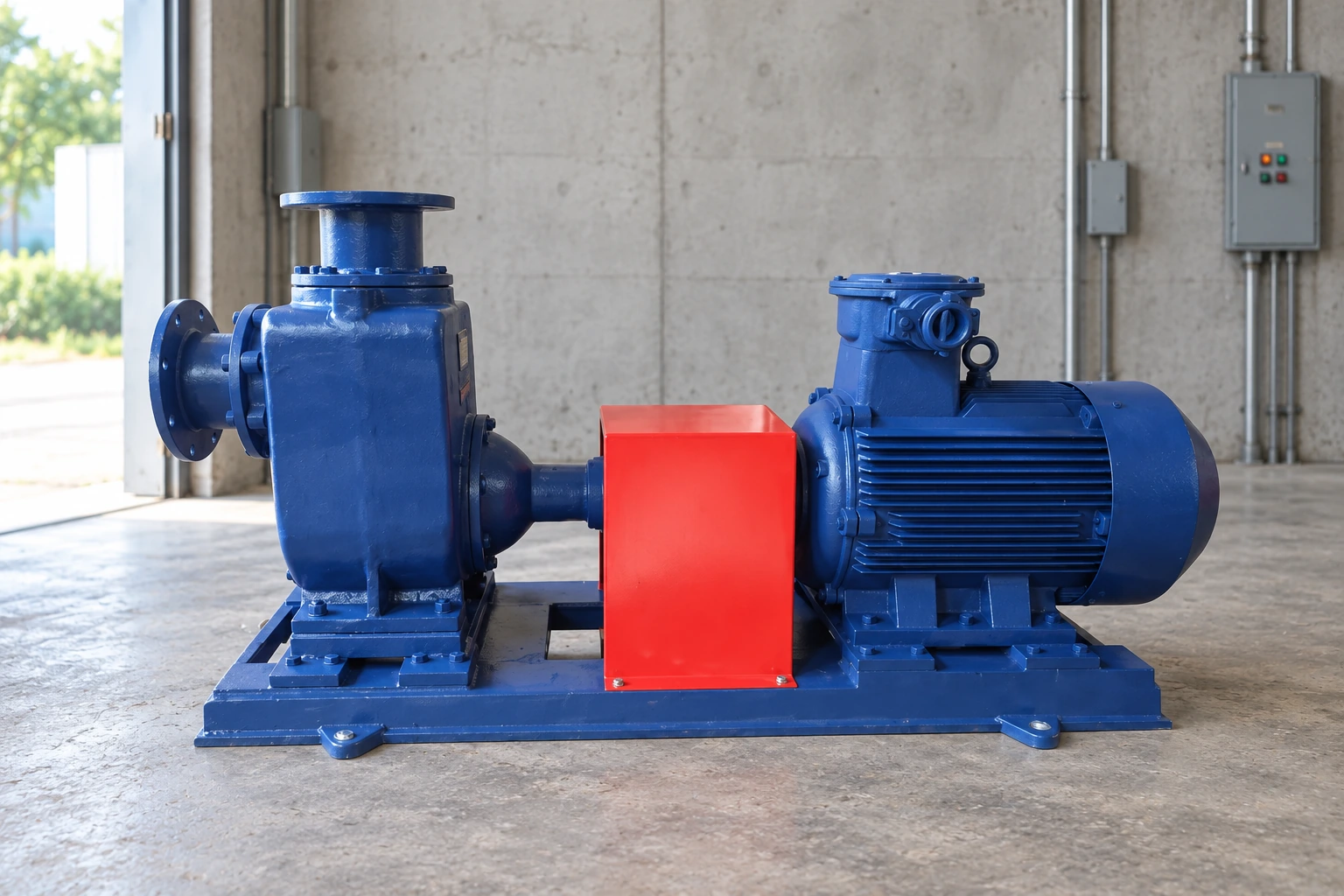
For an example of the equipment category, review the IS clean-water centrifugal pump range. The product image identifies the pump family only. It does not establish the fitted coupling, guard dimensions, suitability for a hazardous area, or compliance of a proposed replacement. Those details require the actual supplied assembly documents.
Separate guarding from isolation
A fixed guard controls access during normal operation. It is not an energy-isolation device. Removing it for alignment, lubrication access or coupling service creates a different work condition that must be controlled before anyone approaches the exposed parts. An emergency stop or an instruction to another operator does not replace the applicable isolation procedure.
In a United States workplace, OSHA’s hazardous-energy control requirements provide the regulatory starting point for servicing where unexpected startup or released energy could injure workers. The employer must determine the applicable procedure and responsibilities. Electrical power, automatic starts, engine starting systems, stored pressure and possible reverse rotation deserve consideration for the particular pump set.
Prepare measurements with the equipment safely stopped and isolated by authorized personnel. Use existing drawings where possible. Never reach through a guard or approach an exposed rotating coupling to estimate dimensions. If a drawing cannot resolve an important feature, arrange an approved inspection rather than improvising while the set runs.
Build a usable dimensional package
Record the coupling’s maximum rotating diameter, overall rotating length and its position relative to fixed mounting points. Include the shaft heights and the baseplate surfaces available for attachment. Identify dimensional tolerances and the approved movement envelope rather than assuming that a nominal coupling diameter is sufficient for fabrication.
Show nearby bearing housings, drain points, lifting features, alignment-tool access and cable routes. A replacement can fit the coupling yet obstruct a routine task, encouraging later removal. Conversely, a large service opening can defeat protection if someone can reach a hazardous part. Treat access and protection as one design review, with the safe servicing method stated explicitly.
Distinguish dimensions measured on the installed set from dimensions copied from a catalog. Record who measured them, when the measurement was taken and which drawing revision applies. If a coupling or motor will change during the same shutdown, use the final assembly envelope. Ordering around equipment that is about to be replaced is a common source of rework.
Specify protection and attachment together
OSHA’s mechanical power-transmission standard addresses hazards associated with rotating shafts, couplings and related equipment. The applicable requirements depend on the installation. Use the standard with the site’s safety assessment and equipment instructions; do not treat a supplier’s phrase such as “OSHA style” as evidence that the finished set has been assessed.
Define the intended fixed supports, attachment method and resistance to foreseeable contact. A guard should not rely on an unstable adjacent pipe, a loose bracket or a component that moves during normal adjustment. Its edges and fasteners must not create cuts, snag points or projections in the access route. The design reviewer should also consider whether maintenance staff could mistakenly use it as a step.
Material selection depends on moisture, temperature, chemical exposure, corrosion, impact and any ignition-risk assessment. Perforation or mesh is not automatically suitable merely because it provides ventilation. Opening size and separation from the hazard need an applicable engineering basis. Do not copy a mesh size from an unrelated machine or assume a painted metal cover suits every environment.
Use an acceptance table before fabrication
The following is a qualitative review checklist, not a substitute for dimensional requirements in the approved guard drawing. The regulatory references above establish the safety context; the equipment and site specialists must define the final acceptance details.
| Review item | Evidence to request | Reason to stop acceptance |
|---|---|---|
| Assembly identity | Pump, motor and coupling identification with current drawing | Guard matches a different coupling or shaft height |
| Reach protection | Reviewed openings and approach directions | Accessible rotating surface remains exposed |
| Internal envelope | Approved dimensions and clearance review | Possible rubbing or interference is unresolved |
| Attachment | Defined brackets, supports and fastener arrangement | Guard moves, loosens or depends on unsuitable support |
| Service access | Written removal and refitting sequence | Routine task requires defeating protection while running |
| Environment | Material and finish matched to documented conditions | Corrosion or ignition questions remain unanswered |
| Final inspection | Signed stationary inspection and controlled startup record | Missing hardware, contact marks or incomplete coverage |
Send this table with the dimensional package when requesting a quotation. Ask the supplier to identify exclusions, supplied fasteners and drawing assumptions. A low price is difficult to compare if one quotation covers only a shell while another includes mounting hardware, engineering review and installation instructions.
Check maintenance access without weakening protection
List the tasks expected during the guard’s life: coupling inspection, shaft alignment, seal replacement, condition monitoring and cleaning around the baseplate. Decide which require removal and how the isolated equipment will be made safe. Convenient access is valuable because an awkward cover is more likely to be left off, but convenience cannot justify an unprotected opening.
For measurement work, coordinate the guard with the selected pump shaft alignment method. Tool brackets and measurement positions may affect temporary service access. The normal running guard still needs to be fully restored after the measurement apparatus is removed. A temporary alignment setup is not the final operational configuration.
Avoid changing brackets simply to make a cover easier to lift unless the new arrangement has been reviewed. Labeling, manageable sections and retained hardware can help the refitting process, but their appropriateness depends on the approved design. Record any components that must be replaced after removal rather than assuming every fastener is indefinitely reusable.
Inspect the stationary installation before startup
Compare the installed guard with the approved revision. Check every attachment point and verify that the cover is stable without distortion. Look for sharp edges, incomplete closures, trapped cables and interference with drains or service points. Inspect the full perimeter from the accessible working positions, using the site’s approved method for assessing reach protection.
Check that the coupling, alignment hardware and nearby components have been assembled correctly before closing the guard. Guard replacement must not conceal unfinished work. If support defects are found, resolve them through the appropriate pump soft-foot correction process rather than using the guard to brace or restrain the set.
Do not manually rotate or move the equipment unless the isolation and maintenance instructions permit that activity. A stationary clearance check is only one part of acceptance. Where tolerances, movement or thermal conditions remain uncertain, obtain engineering clarification before a controlled startup. Uncertainty should result in a documented hold point, not an assumed pass.
Return the pump set to service deliberately
Before release, confirm that tools and loose parts have been removed, the work area is clear, all required guarding is restored and the site’s authorization process is complete. The startup must follow the operating procedure with personnel outside hazardous areas. Do not run with the guard removed to see whether a noise disappears.
During the controlled observation, look for abnormal noise, contact, looseness or unexpected vibration from a safe position. If a problem develops, stop through the approved process and investigate after isolation. A rubbing guard may indicate a dimensional error, movement or incorrect installation. Bending the cover away while the pump runs is not an acceptable diagnostic method.
Keep a closeout record containing the drawing revision, installation date, inspection findings, remaining restrictions and responsible acceptance signatures. For a broader inspection schedule, connect this record with the dewatering pump maintenance plan. Reassess the guard after a motor, coupling, baseplate or access-platform change, even if the old cover still bolts into place.
Further learning
The WorkSafe machinery-guarding presentation below uses agricultural equipment to introduce access hazards and protection principles. It supports recognition of access hazards; it does not approve a pump-specific fabrication drawing or replace the site’s assessment and isolation procedure.

Frequently asked questions
Can a coupling guard be selected by motor power alone?
No. Motor power does not establish coupling diameter, rotating length, shaft height, mounting points or approach distances. Use the actual assembly and a reviewed dimensional package, including the environment and maintenance access requirements.
Is a smooth coupling safe to operate without a guard?
A smooth appearance does not remove the entanglement hazard of rotating surfaces. The responsible safety assessment and applicable requirements determine protection. Do not treat the absence of projecting bolts as permission to expose the rotating connection.
Can a guard remain off during an alignment check?
Only within an authorized servicing procedure with the necessary isolation and controls. Complete the measurements and restore the approved operational guard before returning the set to service. Do not assume a stopped motor cannot restart automatically.
Does a catalog compliance statement approve the installation?
No. A catalog statement does not confirm the fit, reach protection, attachment or environmental suitability of the assembled pump set. Request the applicable design basis and complete the installation acceptance review.
When should the guard be reviewed again?
Review it after changes to the coupling, motor, baseplate, guard mounting or nearby access arrangements, and after damage or contact marks are found. Include routine condition checks in the site’s maintenance program and retain evidence of corrections.