
Centrifugal pump shutoff head is the differential head a pump develops at zero delivered flow, at a stated speed and impeller diameter. It is a point on the pump performance curve, not the normal operating duty and not permission to run with a closed discharge. To assess pressure, combine the appropriate pump head with the suction pressure and the liquid density, then check every exposed component against its applicable pressure limit. The assessment must include credible operating conditions and transient pressure, rather than treating a catalog maximum as a complete system design.
Keep shutoff head separate from rated head
Rated head belongs to a specified duty, normally paired with a rated flow. Shutoff head belongs to the zero-flow condition. Many centrifugal pump curves rise as flow decreases, so shutoff head can exceed the head at the selected duty. The relationship depends on the actual curve. There is no universal percentage that safely replaces the manufacturer’s documented information for every impeller, speed, or pump design.
A catalog may list maximum head and maximum flow in different columns. Those values commonly describe different points. They do not establish a duty that delivers maximum flow at maximum head. Obtain the complete curve with model, speed, liquid conditions, impeller diameter, and any operating restrictions identified. The centrifugal pump curve reading guide explains how these conditions define the chart you are using.
Find the zero-flow point on the correct curve
Locate zero flow on the horizontal axis and follow it to the relevant head curve. Read the head from the vertical scale, retaining the unit. If several impeller diameters or speeds appear, identify the supplied configuration before recording a value. An unmarked screenshot can easily lead a buyer to quote the highest curve even when the offered assembly uses a different impeller.
Where the chart stops short of zero flow, request the shutoff value from the supplier. Do not extend the line by eye and report the result as certified performance. Similarly, a maximum working pressure printed on a casing is a component limit, not the head the pump necessarily generates. Keep performance information and pressure-rating information in separate fields within the procurement record.
The Hydraulic Institute’s explanation of NPSH and pump operating regions is useful here: the available curve and the region approved for operation are related but different concepts. A plotted endpoint is not automatically an approved continuous operating point.
Convert head to differential pressure carefully
The relationship is differential pressure = liquid density × gravitational acceleration × differential head. In SI units, pressure in pascals equals density in kilograms per cubic metre multiplied by approximately 9.81 metres per second squared and head in metres. Divide pascals by 100,000 to obtain bar. Use the density at the relevant liquid temperature, particularly when assessing liquids other than ordinary cold water.
For an illustrative water calculation, assume density of 1,000 kg/m³ and a documented shutoff head of 60 m. Differential pressure is approximately 588,600 Pa, or 5.89 bar. If the applicable suction pressure is 2.0 bar gauge and the simplified assessment uses comparable pressure-reference elevations, the discharge pressure is approximately 7.89 bar gauge. This example is arithmetic only; it does not specify a BORRAPUMP model or its rating.
For actual equipment, account for the gauge locations, elevation, operating speed, and pressure reference consistently. A designer may need to include velocity-head terms when comparing measurements taken during flowing operation. At shutoff, a simple head-to-pressure conversion can be useful, but the conditions behind the value must still match the installation being assessed.
Include the highest credible suction pressure
A pump adds energy to the liquid entering it. Consequently, discharge pressure cannot be judged from pump head alone where the inlet is pressurised. Review the maximum credible upstream pressure, not only the inlet pressure seen during a convenient daytime test. Supply-zone changes, tank levels, upstream pumps, and operating sequences can change the condition presented to the pump.
If pumps are arranged in series, the downstream pump may receive an inlet pressure elevated by the upstream pump. Obtain a coordinated assessment of the complete train. Do not assume that a downstream casing is protected simply because its own differential head is modest. In a multistage unit, use the complete assembly’s documented curve and pressure limits rather than multiplying a guessed single-stage value.
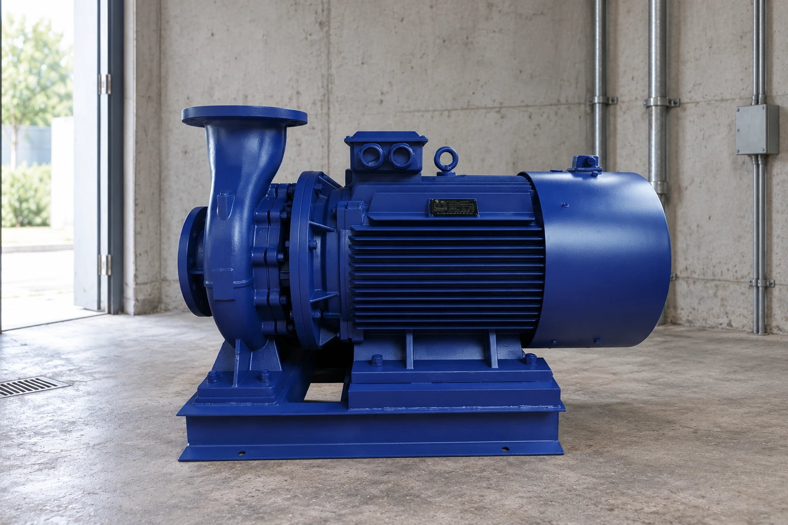
A product such as the IS clean-water centrifugal pump provides a route for requesting model-specific information. Ask for the offered impeller, speed, curve, casing rating, and seal arrangement. The product image or family name cannot establish the allowable pressure of the exact unit being purchased.
Check the entire pressure boundary
The casing is only one part of the system. Flanges, gaskets, valves, instruments, flexible connectors, seals, and connected pipework may have different allowable pressures. Temperature, materials, condition, and the applicable specification can affect those limits. The lowest relevant limit can govern the assessment even if the main pump casing has adequate margin.
| Assessment item | Information to obtain | Decision it supports |
|---|---|---|
| Pump configuration | Supplied curve, speed, impeller and shutoff head | Establish the correct differential head |
| Inlet condition | Maximum credible suction pressure and reference location | Estimate the discharge pressure boundary |
| Liquid | Density, temperature and compatibility | Convert head and apply appropriate ratings |
| Connected equipment | Applicable pressure limits for each component | Identify the governing pressure constraint |
| Controls and transients | Operating sequences, trips and surge assessment | Review conditions beyond a steady curve point |
This table is a document checklist, not a list of universal acceptance limits. Each project needs values from its responsible designer and equipment documentation. A pressure switch setting alone does not replace the pressure-boundary review or demonstrate protection against every failure scenario.
Do not treat shutoff as a normal running condition
At zero delivered flow, input energy can heat the trapped liquid and the pump. Internal recirculation, vibration, seal distress, or other damage can occur depending on the design and conditions. An allowable brief test duration, if any, must come from the manufacturer’s instructions and the approved procedure. Do not invent a safe number of seconds from a general article.
Normal low-demand operation should be assessed using the documented minimum-flow requirements and the approved control arrangement. The minimum-flow guide addresses that separate operating question. A bypass is not automatically adequate: its capacity, destination, pressure differential, and thermal consequences need to be established for the actual system.
The US Department of Energy’s pump systems resources support assessing the pump together with the system. Buying a higher-head pump to solve an uncertain flow problem can increase pressure exposure and energy use without correcting the underlying issue.
Review speed changes and exceptional conditions
A variable-speed drive changes the curve, but the assessment should use the highest permitted operating speed and the complete set of credible sequences. Verify whether bypass operation, manual mode, replacement controls, or a control fault can produce a different condition. Record which conditions are design cases and which are prevented by a documented protective function.
Affinity relationships can support preliminary analysis of the same pump under suitable assumptions, but they do not replace the supplier’s limits or validate operation outside an approved range. Do not extrapolate performance to a higher speed without checking mechanical, motor, seal, suction, and pressure constraints. The supplier must confirm the configuration and the designer must approve the system application.
Transient pressure is another separate question. A steady shutoff value does not capture every event caused by fast valve movement, check-valve closure, pump trip, or a long pipeline. Where those events matter, request a surge assessment and appropriate mitigation. The purpose is to examine the credible pressure envelope rather than attach a generic margin to one catalog value.
Prepare a useful supplier enquiry
Send the required duty flow and head, the liquid and temperature, the suction-pressure range, installation elevations, supply frequency, speed-control method, and connected-equipment pressure limits. Ask the supplier to identify the offered model, impeller, shutoff head, approved operating region, minimum flow, and maximum applicable working pressure. Keep the curve revision with the quotation.
During commissioning, compare recorded conditions with the approved documents. Unexpected head should trigger a review of speed, gauge accuracy, reference elevations, valve positions, and the installed configuration before anyone changes a setting. Use the duty-point calculation guide for the flowing duty; use the shutoff assessment for its specific zero-flow pressure question. These records answer different questions and should remain distinguishable.
Further learning
NPTEL’s lecture, “Mod-01 Lec-15 Characteristics of a Centrifugal Pump,” explains the performance-curve background used in this article. It provides engineering context rather than a model-specific test procedure. The written checks above remain necessary even when a video illustration appears similar to the installation.

Frequently asked questions
Is shutoff head the same as maximum discharge pressure?
No. Shutoff head is differential head at a stated configuration. Discharge pressure also depends on the suction pressure, liquid density, measurement references, and the condition being assessed. Connected components and transients require their own checks.
Can a centrifugal pump run continuously at shutoff?
Do not assume it can. Obtain the manufacturer’s operating restrictions and use the approved system controls. A curve endpoint does not establish an allowable duration, and a short test procedure does not authorise continuous operation.
Can I calculate shutoff head from rated head alone?
A universal multiplier is not reliable. Use the actual curve or obtain the documented value for the supplied impeller and speed. If that information is absent, keep the procurement assessment open rather than inventing a value.
Does a pressure switch make the pressure rating irrelevant?
No. The pressure boundary still needs to withstand the applicable design conditions. Controls, protective devices, component ratings, and operating sequences must be assessed together by the responsible designer.
Does this guidance replace fire-pump churn testing rules?
No. Fire pumps have specific acceptance, inspection, and operating requirements. Use the dedicated fire-pump churn pressure guide and the standards and procedures applicable to that installation.