
Before work begins, identify whether the activity is a receiving review, installation check, functional test, periodic inspection, or handover record review. The scope changes the evidence needed.
Direct Answer
A diesel fire pump inspection starts with the approved project documents, then checks the supplied package, engine interfaces, controller information, water path, test arrangement, and records. This article is a project-review aid for contractors, owners, distributors, and procurement teams. It does not replace an engineer, authority, commissioning plan, or the equipment manufacturer’s verified documentation.
1. Establish the Review Boundary
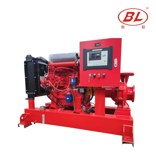
Before work begins, identify whether the activity is a receiving review, installation check, functional test, periodic inspection, or handover record review. The scope changes the evidence needed. For a diesel fire pump, the review package should identify diesel driver, coupling or drive arrangement, fuel-system scope, cooling arrangement, controller interface, suction and discharge connections. A missing interface should be logged as a project question rather than filled with an assumed value.
The diesel-driven main pump is a fire-demand machine. It is not sized, started, or accepted from a generic checklist alone. Keep package-supply information distinct from field-installed piping, electrical work, supports, drainage, ventilation, and authority coordination.
2. Start With Controlled Documents
Use the current approved drawing revision and equipment schedule as the reference point. Confirm equipment tags, driver type, controller reference, connection orientation, and the intended test arrangement. Marking up a superseded drawing can create a false pass because connections and responsibilities may have changed after procurement.
| Review item | What the project team confirms |
|---|---|
| Approved basis | Compare the latest drawing, specification, and equipment schedule before inspecting hardware. |
| Package identity | Match pump, driver, controller, and supplied accessories to the documented package scope. |
| Engine interfaces | Review fuel, ventilation, exhaust, cooling, battery, and service-clearance interfaces against the project design. |
| Water path | Trace source, suction, discharge, valves, gauges, relief or test connections as shown by the project. |
3. Review the Water and Mechanical Path
Trace the water path from the available source through the pump connection and downstream arrangement. The purpose is to locate interfaces and access points, not to declare hydraulic adequacy from a photograph. Check that valve positions, gauges, drains, test connections, and field transitions are identifiable in the project information.

Where an engine-driven package is used, the physical package still has site interfaces. A delivery checklist should distinguish supplied components from items installed by others so that a missing field connection is not mistaken for a missing factory component.
4. Check Driver, Controller, and Utility Interfaces
Review labels, manuals, wiring information, battery or starting provisions, fuel and cooling interfaces, alarms, and access clearances only against the specified package and project documents. Do not state compliance, certification, runtime, or start sequence without verified evidence. Any discrepancy should be routed through the project review process.
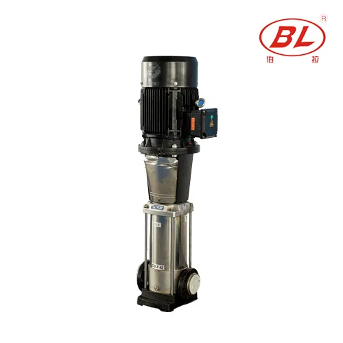
For pressure-maintenance equipment, distinguish the sensing connection and controller response from the main pump controls. For diesel equipment, distinguish engine-support interfaces from the hydraulic pump duty. These boundaries make test observations usable at handover.
5. Plan the Test Before Operating
A useful test plan names the responsible parties, isolation boundaries, communication method, safety controls, observation points, record form, and stop criteria. Verify that the project has defined how water is handled during a test and how the equipment is returned to its required state afterward. Never use a general web article as an operating instruction.
| Before testing | During testing | After testing |
|---|---|---|
| Confirm drawing revision, procedure, access, and roles. | Observe only the documented sequence and record relevant conditions. | Restore the documented configuration and submit exceptions for review. |
| Check safe test and drain path. | Keep unrelated changes outside the test scope. | File records with equipment and drawing references. |
6. Use Procurement Data Carefully
For a replacement, expansion, or new package inquiry, provide the required flow and pressure, water source, driver requirement, controller requirement, electrical data where applicable, connection preferences, destination, documents requested, and applicable project constraints. A product family may be a suitable route only after the duty and interfaces are checked.
See the BORRAPUMP Fire Pump guide for related resources, or contact BORRAPUMP with controlled project data for package discussion.
7. Fit and Compliance Boundary
This guide does not certify a fire-protection system and does not claim approval to any named standard or local authority. Final selection, installation, testing, and acceptance require the applicable project documents, responsible professionals, authorities, and verified product evidence.
FAQ
Can a generic guide approve a fire-pump installation?
No. Approval and acceptance depend on the current project documents, applicable authority requirements, and verified equipment evidence.
What documents should be available before a test?
Use the approved drawing, equipment schedule, controller documentation, project test procedure, and required record forms.
Is a jockey pump the main fire-flow pump?
No. Its role is pressure maintenance for small losses; the main fire-pump duty is defined separately by the project.
Should setpoints be copied from an online article?
No. Control values and sequences must come from the approved project design and verified controller documentation.
What should be recorded when an exception is found?
Record the observation, drawing or equipment reference, location, responsible review party, and required follow-up under the project process.
Can a supplier package drawing replace the system drawing?
No. A supplier drawing describes package scope; the engineer’s accepted system drawing defines the installation.