
A pump’s best efficiency point, or BEP, is the flow and head at which the stated pump configuration achieves its maximum hydraulic efficiency. It is a reference point on a performance curve, not a promise that an installation will operate there. The system determines the actual operating point, while the manufacturer defines the permissible operating limits for the pump. Good selection considers how much time the installation spends near an efficient, reliable region and whether every credible condition stays within approved limits. Do not use an unexplained universal percentage around BEP as a substitute for the offered pump’s documentation.
This guide concerns centrifugal-pump selection and operating review. It distinguishes peak efficiency, preferred operation and permitted operation without prescribing a numerical limit for an unverified model.
Identify the configuration behind the efficiency peak
Find the correct curve for the proposed impeller diameter, speed, stage arrangement and liquid. The efficiency peak belongs to that configuration. A family chart may contain several head curves and efficiency contours, so a peak from one impeller must not be assigned to another. Confirm whether efficiency means pump hydraulic efficiency or a combined pump-and-motor figure.
Record the reference flow, head, efficiency and shaft power at BEP. Keep the chart revision and test basis with the selection record. A round percentage on a sales page cannot identify a useful operating envelope. The pump curve reading guide explains the other information that should be read alongside the efficiency line.
Distinguish three different concepts
BEP is a point, the preferred operating region is a range, and the allowable operating region is another range defined through the applicable assessment. Their boundaries and conditions are not interchangeable. The manufacturer’s approved operating limits may depend on vibration, temperature rise, hydraulic loading, suction behaviour and other design constraints.
A pump operating outside the preferred region is not automatically described correctly by a single universal failure rule. Equally, operation within a broad allowable range does not mean every point is equally efficient or desirable for continuous service. Request the actual guidance for the selected equipment and the expected duration at each duty. Use the Hydraulic Institute explanation of operating regions as background, then apply the supplier’s model-specific information.
Locate the installed duty on the chart
Calculate or measure the system requirement and find its intersection with the pump characteristic. Mark the resulting flow relative to the BEP flow for the same speed and impeller. A project requirement written as a nominal flow and pressure does not establish what the installed equipment will actually deliver.
Source level, destination pressure, valve position and filter condition can all shift the operating point. A commissioning test with a nearly closed valve may show a different condition from the normal service duty. Record the system state for each measurement, and compare a representative duty profile rather than selecting whichever test point looks closest to the peak.
The centrifugal minimum-flow article addresses the low-flow end separately. Minimum flow is a protection requirement; it should not be confused with an efficiency target.
Evaluate the full demand profile
List the operating cases and annual hours associated with each one. Include ordinary demand, low demand, peak demand, standby changeover and relevant source-level extremes. For parallel arrangements, check the duty with different pump counts. The same unit can operate in different parts of its curve as the system and control sequence change.
An installation with occasional peak demand may benefit from different staging than one that spends nearly all its time near maximum flow. Avoid adding successive safety allowances to head and flow without checking their effect. An oversized selection can force persistent throttling or move the unit into an undesirable low-flow region during routine operation.
| Review question | Evidence needed | Practical consequence |
|---|---|---|
| Where is BEP? | Correct efficiency curve | Establishes the reference point |
| Where does normal duty fall? | System curve or measurements | Shows routine efficiency and loading |
| What is the preferred range? | Manufacturer guidance | Supports continuous-operation selection |
| What are the absolute limits? | Approved operating envelope | Determines protection and restrictions |
| How long is each case used? | Demand and operating-hour record | Supports an annual energy comparison |
| What changes during failure? | Duty/standby and control sequence | Tests service continuity within limits |
The table is a review process, not a source of universal flow percentages. Numerical limits must come from the selected equipment’s accepted documentation.
Understand the low-flow concerns
Moving left of BEP may involve internal recirculation, greater temperature rise, pressure fluctuations or changed radial loads, depending on design and condition. These are reasons to obtain minimum-flow and operating-region guidance. They are not instructions to run an uninstrumented test to discover a limit.
A bypass can protect minimum flow in a suitable design, but it also circulates energy without necessarily providing useful service. Include the bypass flow and power in the system assessment. Do not increase flow merely to approach BEP if doing so violates the process requirement or overpressurizes downstream equipment. The solution may involve a different pump, speed, impeller selection or staging arrangement.
Check the high-flow end independently
At a lower system resistance, the operating point may move rightward. Required inlet conditions and shaft loading can change, and an apparently attractive higher flow may exceed a documented limit. Check NPSH, motor loading and the entire approved envelope rather than judging acceptability solely from efficiency.
The NPSH comparison guide explains why inlet assessment remains necessary. A pump does not become protected from cavitation simply because its calculated duty lies near BEP. The available suction head comes from the actual source pressure, level, temperature and route, while the required information comes from the pump documentation.
Compare selection alternatives at equivalent duties
Compare candidate pumps at the same required flow and head and under the same operating cases. Include motor and drive efficiency if comparing electricity rather than pump hydraulic efficiency. A smaller pump closer to its efficiency peak may still be unsuitable if it cannot meet a legitimate extreme duty or lacks the required materials and solids capability.
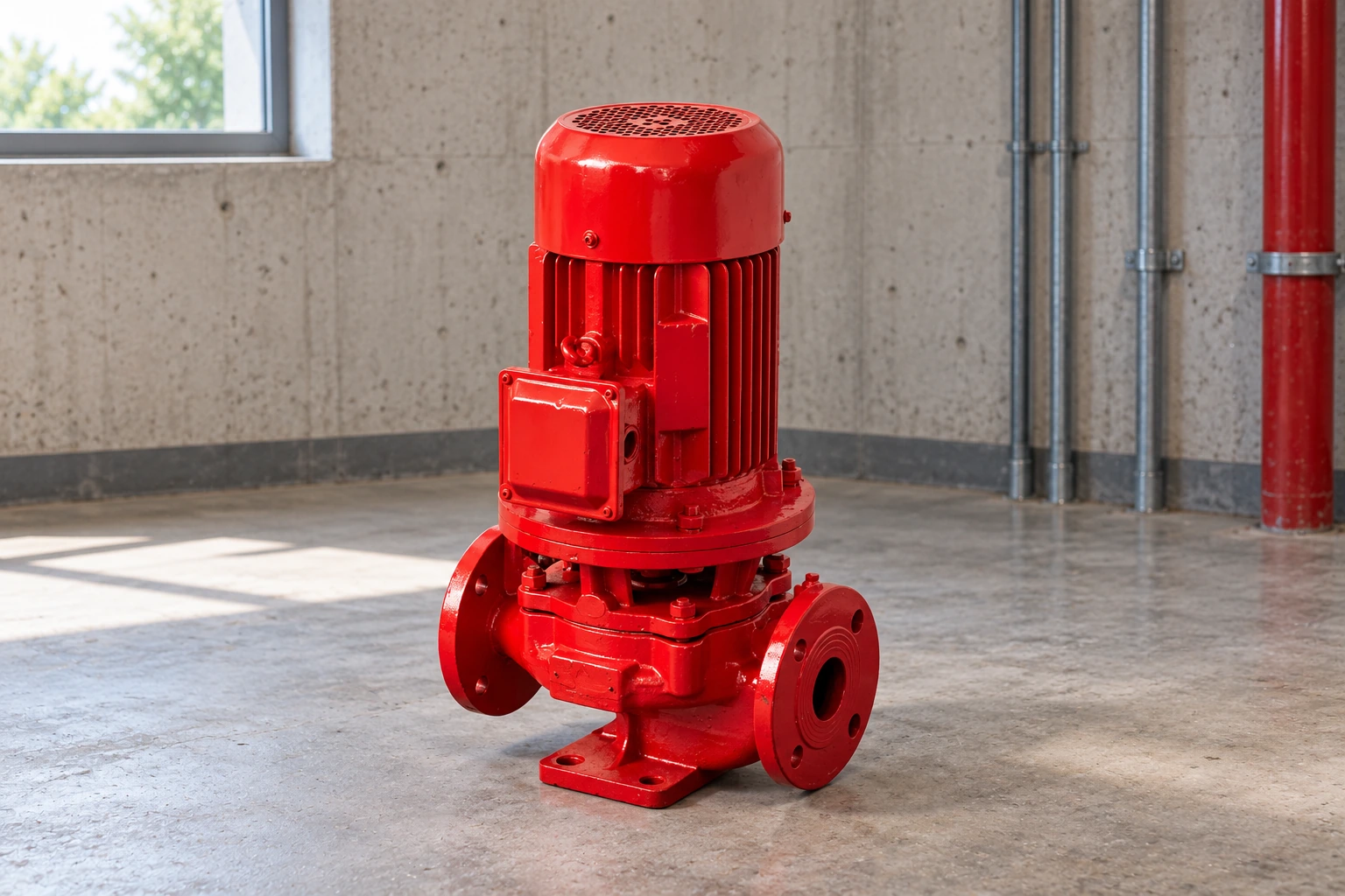
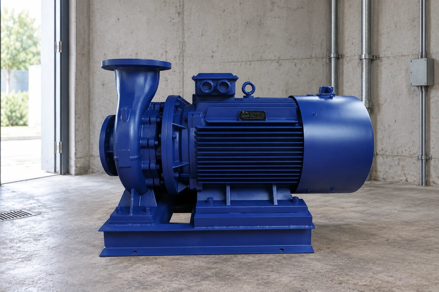
An IS clean-water centrifugal pump is a relevant product family for evaluating clean-water transfer. The displayed range does not establish the BEP or operating limits of a particular model. Send the measured or calculated duty cases and ask for the matching curve, permitted range and power data for the exact offered configuration.
Use controls to maintain service and acceptable operation
A variable-speed drive can help a suitable pump follow changing demand, but the allowable speed range and hydraulic envelope still apply. Multiple smaller pumps can provide staging flexibility, although parallel interaction and minimum-flow conditions need checking. A pressure controller alone does not guarantee that the active pump remains within a preferred region.
Specify the sequence for starting another pump, stopping a pump at low demand and responding to inadequate inlet pressure. Include sensor failure and restart behaviour. The efficiency objective should work with stable service and equipment protection. An energy-saving setting that produces hunting, repeated starts or loss of service has not solved the operating problem.
Check the result with measured evidence
During commissioning, record flow, differential head, speed and electrical input together. Capture tank levels and relevant valve positions. Compare the measured point with the accepted curve and verify instruments before diagnosing a pump defect. Vibration, temperature and other condition observations should follow the manufacturer’s and site’s procedures.
For an existing installation, compare performance at the same duty over time. A falling efficiency may reflect wear, obstruction, liquid changes or measurement error. A changed system curve can also move a sound pump away from its earlier point. The DOE pumping-system sourcebook supports a system-level review rather than replacing equipment based on one isolated efficiency number.
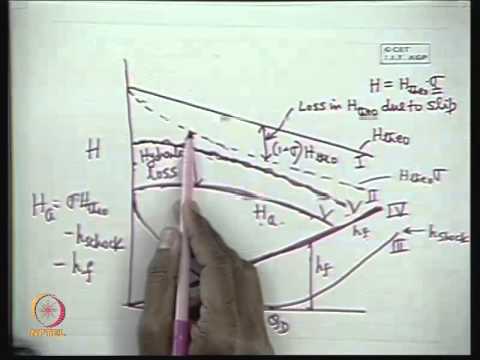
Further learning: NPTEL explains centrifugal pump characteristics. Use this educational background with the model-specific data and method discussed above; the lecture does not certify a BORRAPUMP model.
Frequently asked questions
Is BEP always the purchasing duty point?
It is a useful reference, but selection must meet the real duty range and the manufacturer’s limits. A nominal duty near BEP cannot compensate for unacceptable operation during other required conditions.
Can I assume a fixed percentage range around BEP?
No. Obtain the appropriate preferred and allowable regions for the selected design and service. An unlabeled percentage copied from another pump may be inappropriate.
Does the efficiency peak include the motor?
Only if the documentation explicitly defines it that way. Pump hydraulic efficiency, motor efficiency and combined electrical efficiency describe different boundaries.
Will a drive keep every pump near BEP?
No. The system, demand, speed range and pump characteristic determine the operating points. Confirm the proposed control sequence across the complete duty envelope.
What should a supplier include in the offer?
Request the exact performance curve, efficiency and power data, BEP reference, operating limits, inlet requirements and the expected behaviour for each supplied duty case.