
Sewage pump wet-well active volume is the usable storage between the normal stop and start levels for a defined pumping stage. It controls how long the well fills before a start and how long the pump runs while drawing that storage down. Size it using the pump’s actual discharge at the duty point, the inflow range, the operating sequence and the motor manufacturer’s cycling limits. The total depth or total tank volume is not the same as active storage, and emergency storage must be evaluated separately from ordinary cycling volume.
This guide develops a simplified constant-speed cycle calculation and explains where it stops being adequate. It does not select final civil dimensions or control elevations without the station’s hydraulic, mechanical and operational information.
Identify the volume that actually participates in cycling
Draw the wet well with the proposed start and stop elevations, pump inlets, incoming sewer, alarm levels and overflow or flooding constraints. Identify the interval used by each control stage. Dead storage below the stop level does not automatically contribute to a normal fill-and-draw cycle.
For a straight-sided well with constant horizontal area, active volume equals plan area multiplied by the elevation difference. Irregular wells, benching, pipe penetrations and internal structures require a volume-versus-level relationship that reflects the actual geometry. Do not apply the outside tank dimensions as if they were unobstructed liquid storage.
Keep this design task separate from a sewage pump drawdown flow test. A test uses observed volume change and time to estimate pumped flow under stated conditions. The present calculation uses an established flow basis to examine the storage and control cycle.
Define inflow and pump flow separately
Let q be incoming sewage flow and Q be the discharge of the operating pump at the relevant duty point. During filling with that pump off, the well gains volume at q. During pumping, the net drawdown rate is Q minus q, provided Q is greater than q.
Use consistent units. For V in cubic meters and Q and q in cubic meters per second, the resulting times are seconds. A capacity quoted in liters per second must be converted before it is used with cubic-meter storage. Record the conversion beside the calculation so an otherwise reasonable formula does not conceal a thousand-fold unit mistake.
The selected Q must come from the actual operating point, not simply a maximum number on a catalog page. The related submersible sewage pump sizing guide addresses the system-duty decision. Active volume cannot compensate for a pump that lacks capacity at the required head.
Derive a simple on-off cycle
For a single operating stage with constant inflow, constant Q and negligible switching delay, the fill time is t_off = V / q. The drawdown time is t_on = V / (Q − q). The total cycle time is their sum. This model applies only while 0 < q < Q.
The longest cycling concern is not necessarily at maximum inflow. In this simplified model, the shortest total cycle occurs at q = Q / 2. At that condition, total cycle time is 4V / Q. Therefore, if the approved minimum complete cycle time is T, a preliminary storage relation is V = Q × T / 4.
This is an arithmetic model of one stage, not a universal design rule. Ontario’s sewage-pumping design guidance discusses wet-well cycling and the importance of manufacturer duty-cycle recommendations. Apply the guidance relevant to the project and examine the actual control sequence before selecting final volume.
Work through a hypothetical example
Assume a constant pump discharge Q of 0.020 m³/s and an engineering-selected minimum cycle time T of 600 seconds. These are example inputs, not ratings or recommendations for a particular pump. The simple relation gives V = 0.020 × 600 / 4 = 3.0 m³.
At q = 0.010 m³/s, the fill time is 3.0 / 0.010 = 300 seconds and the pumping time is 3.0 / (0.020 − 0.010) = 300 seconds. The complete cycle is 600 seconds. At q = 0.005 m³/s, filling takes 600 seconds and pumping takes 200 seconds, giving an 800-second cycle.
These calculations illustrate why the inflow range matters. They do not demonstrate acceptable detention, emergency storage, submergence or starts per motor in a real alternating station. If the actual Q changes materially as the water level moves, use an appropriate level-dependent calculation rather than silently retaining the constant-flow assumption.
Check the actual pump sequence
Document lead and lag operation, alternation, standby availability, restart delays and any variable-speed control. Two pumps alternating starts do not behave identically to one pump receiving every start. The station’s cycle frequency and the starts experienced by each individual motor must be distinguished in the review.
If a second pump starts before the lead pump reaches its stop elevation, divide the calculation into the actual stages. Parallel discharge cannot always be assumed to equal twice the single-pump flow, because the operating point changes with the system. Use the relevant combined operating condition and level intervals.
The duplex sewage pump control guide provides the wider sequence context. Verify the active-volume model against that sequence before translating it into settings. A simple equation should not obscure a control action that changes which pumps run or which storage interval is used.
Balance cycling against other storage requirements
Increasing the start-stop interval can lengthen a simple cycle, but a deeper or larger operating zone has other consequences. Review inlet conditions, retention, solids behavior, odor control, required pump submergence and access. More storage is not an unlimited substitute for a correctly selected pump and control strategy.
Separate normal operating storage from alarm response and emergency retention. State where the emergency-storage calculation begins and what inflow and response period it uses. Do not count the same volume twice in a summary that claims both normal cycle storage and a full independent emergency allowance.
The Atlantic Canada sewage design guidelines provide additional pumping-station design context. Regional guidance can have different assumptions and requirements. Record which authority and edition govern the project rather than combining isolated numerical recommendations from unrelated jurisdictions.
Use a review table before changing levels
| Review item | Evidence required | Common mistake to avoid |
|---|---|---|
| Active volume | Actual volume-versus-level relationship | Counting dead or obstructed volume as usable storage |
| Pump discharge | Duty point for each operating stage | Using catalog maximum flow |
| Inflow | Initial, normal, seasonal and design conditions | Checking only peak inflow |
| Cycling | Manufacturer limits and actual sequence | Confusing station cycles with starts per motor |
| Low level | Required submergence and shutdown behavior | Lowering stop level solely to obtain more volume |
| High level | Incoming sewer, alarm and flooding constraints | Raising start level without reviewing upstream effects |
| Emergency storage | Separate basis and response assumptions | Counting normal and emergency volume twice |
Resolve the missing inputs before changing a setting. A controller can accept a new number even when the hydraulic or operating basis for that number is incomplete. The approval should address the whole stage and its consequences, not only the arithmetic storage result.
Turn the design into a commissioning record
Record the approved volume curve, control levels, pump combinations and expected operating conditions. Verify the installed level instruments and their reference datum. A correct elevation in one drawing can still be applied incorrectly if the installer and controls technician use different zero references.
During commissioning, observe the actual fill and run periods under recorded conditions. Compare the observations with the design model and investigate meaningful differences. Document changes in flow, control delay or available geometry before revising the calculation. A short demonstration under one inflow does not verify every seasonal operating condition.
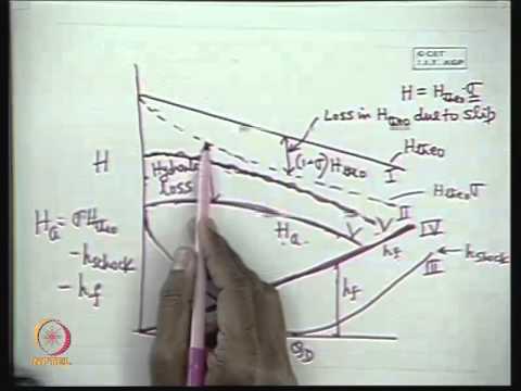
For a submersible sewage pump package, confirm the quoted equipment’s duty, permitted operation and cycling recommendations with the supplier. Identify the supplied model and serial number so the equipment documentation matches the proposed station. Further learning: NPTEL’s centrifugal-pump characteristics lecture helps explain why Q depends on the system rather than remaining a fixed catalog maximum.
Frequently asked questions
Is the whole wet-well volume available for cycling?
No. Identify the usable storage between the relevant normal start and stop elevations. Volume below the stop level, above a selected stage or occupied by internal structures may serve other purposes. Use the installed geometry and keep each storage definition separate in the report.
Why can intermediate inflow cause frequent cycling?
In the simple constant-flow model, a midrange inflow can produce both relatively short filling and short drawdown periods. The minimum total cycle occurs at half the operating pump discharge. Real stations need additional checks when sequencing, variable speed or changing hydraulic conditions alter that model.
Can the stop level be lowered to increase active storage?
Only after reviewing the supplied pump’s required submergence, inlet conditions, instrument behavior and operating limits. Lowering a setting solely to obtain more volume can create an unacceptable low-level condition. Obtain an approved level schedule for the complete station.
Does the example specify a ten-minute cycle for every pump?
No. Six hundred seconds is a hypothetical input used to demonstrate the calculation. The required minimum cycle time and permitted starts must come from the governing design basis and equipment manufacturer. Different motors, pump arrangements and control modes can require a different review.
What should be requested from the station designer?
Request the volume curve, inflow cases, duty points, operating sequence, starts assessment, approved elevations and separate emergency-storage basis. Include assumptions and limitations so commissioning staff can compare observed operation with the same model rather than relying on an unexplained tank size.