
A booster pump installation should be planned from the required flow and target pressure, then checked against the inlet water condition, pipe layout, controls, protection devices and service access before any equipment is ordered or pipe is cut.
For most building water-pressure projects, the practical layout is source or break tank, suction isolation, pump set, check valve, pressure measurement point, pressure tank branch if used, discharge isolation and the building distribution line. The exact construction drawing still belongs to the project engineer and the local plumbing or electrical authority.
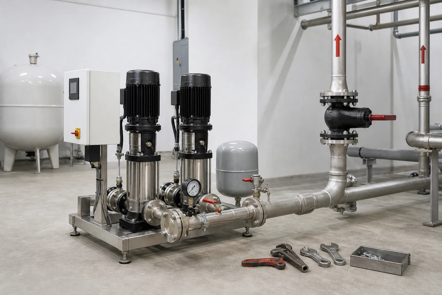
Réponse rapide : Utilisez le mot-clé de l'article pour décrire le problème, mais dimensionnez la pompe en fonction du débit, de la pression/hauteur manométrique, des conditions d'aspiration, du fluide, de l'alimentation électrique et du mode de commande. Pour les systèmes d'incendie ou de surpression régulés, la réception définitive doit provenir de documents spécifiques au projet.
Table des matières
- Part 1. Start with the duty point, not the pump model
- Part 2. Typical booster pump installation order
- Part 3. Installation checks before commissioning
- Part 4. Mistakes that cause unstable pressure
- Part 5. Borra product fit and quotation path
- FAQ
Part 1. Start with the duty point, not the pump model
The first installation decision is not whether the pump is blue, vertical or horizontal. It is the duty point: required flow, target discharge pressure, available inlet pressure and the pipe losses between the source and the furthest demand point. A pump can only behave well when those values are realistic.
For a quotation, provide peak flow, normal flow, incoming pressure range, required outlet pressure, pipe size, voltage, phase, control preference and duty cycle. If a building has zones, roof tanks or variable demand, include that information before a supplier sizes the pump set. This prevents the common mistake of selecting from pipe diameter or motor power alone.
Installation data to confirm
| Entrée | Pourquoi c'est important |
|---|---|
| Peak and normal flow | Prevents undersizing or oversizing the pump set. |
| Incoming pressure range | Determines whether the pump has enough suction condition. |
| Target outlet pressure | Defines the required head after pipe losses. |
| Bloc d'alimentation | Controls motor, controller and protection selection. |
| Service clearance | Allows valve operation, motor service and tank maintenance. |
Part 2. Typical booster pump installation order
A concept sequence is water source, suction valve, optional strainer or flexible connector, pump inlet, pump discharge, check valve, pressure sensor or pressure switch, pressure tank branch, discharge isolation valve and distribution line. Some packaged systems combine several of these parts on one skid, but the function is the same.
The check valve is usually placed on the discharge side to stop reverse flow through the pump. A pressure tank is normally connected on the controlled pressure side so it can buffer demand changes. If the tank is placed on the wrong side of a check valve, the system may not see the stored pressure correctly and the pump can short cycle.
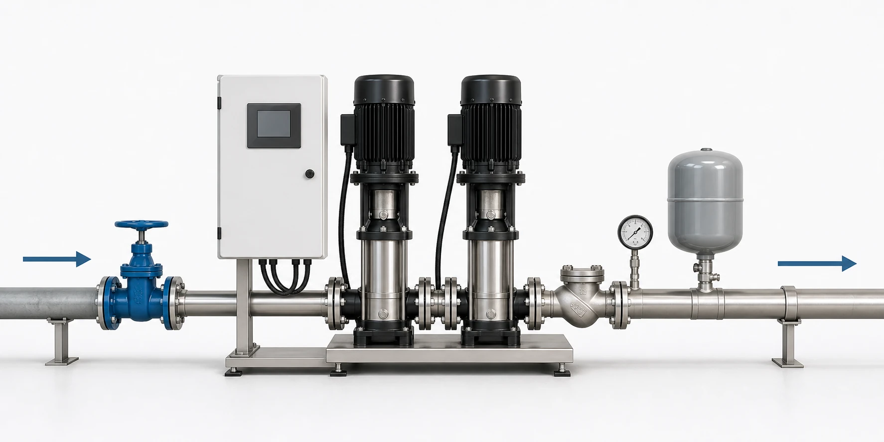
Astuce : Put service valves where a technician can isolate the pump and tank without draining the whole building.
Part 3. Installation checks before commissioning
Before first start, confirm that the pump is anchored, piping is supported independently, valves are open in the intended positions, the pump is primed or vented as required, and the motor rotation is correct. Check that the controller reads the correct pressure point and that any low-water or dry-run protection is wired to the intended signal.
During commissioning, record suction pressure, discharge pressure, motor current, noise, vibration, start/stop values and tank pre-charge if a pressure tank is used. These records give the maintenance team a baseline and help the supplier diagnose unstable pressure later.
Commissioning record
| Check | Pass indicator |
|---|---|
| Rotation and priming | Pump starts without dry running or reverse rotation. |
| Suction and discharge pressure | Values match expected duty range. |
| Tank pre-charge | Aligned with pressure switch or sensor strategy. |
| Current draw | Within motor nameplate and design expectation. |
| Leak and vibration check | No abnormal noise, movement or pipe stress. |
Astuce : Use flow and head data for sizing; pipe diameter and motor power are not enough.
Part 4. Mistakes that cause unstable pressure
Most failed installations are not caused by a single bad component. They come from poor inlet conditions, undersized suction piping, a missing or leaking check valve, an incorrectly charged tank, wrong controller settings, or no allowance for minimum stable flow. A booster pump cannot fix a water source that is already starved.
Do not treat a concept diagram as a permit drawing. Local code, backflow requirements, electrical rules, seismic anchoring, relief protection and the manufacturer manual must control the final installation. This article is for selection and layout discussion, not a substitute for the project drawing.
Common installation issue
| Symptom | Likely cause |
|---|---|
| Rapid start-stop cycling | Small or mischarged tank, leak, or narrow pressure band. |
| Low outlet pressure | Wrong duty point, suction starvation or excessive pipe loss. |
| Noisy operation | Air, cavitation, poor support or valve restriction. |
| Pressure overshoot | Controller setting or sensor location problem. |
Important : Final piping, electrical connection, relief protection and backflow arrangements must follow the project engineer, local code and the product manual. A blog diagram is not a construction drawing.
Part 5. Borra product fit and quotation path
Borra's water supply booster pump starting points include packaged booster regulator equipment, vertical multistage pumps and inline booster pump options. For a practical recommendation, send the project flow, pressure/head, inlet condition, water quality, power supply, duty cycle and installation space.
If the project involves fire protection, high-rise zoning, pressure vessels or local authority review, keep the wording conservative until the project engineer confirms the applicable standard and documentation scope. Do not rely on a generic pump name to claim approval.
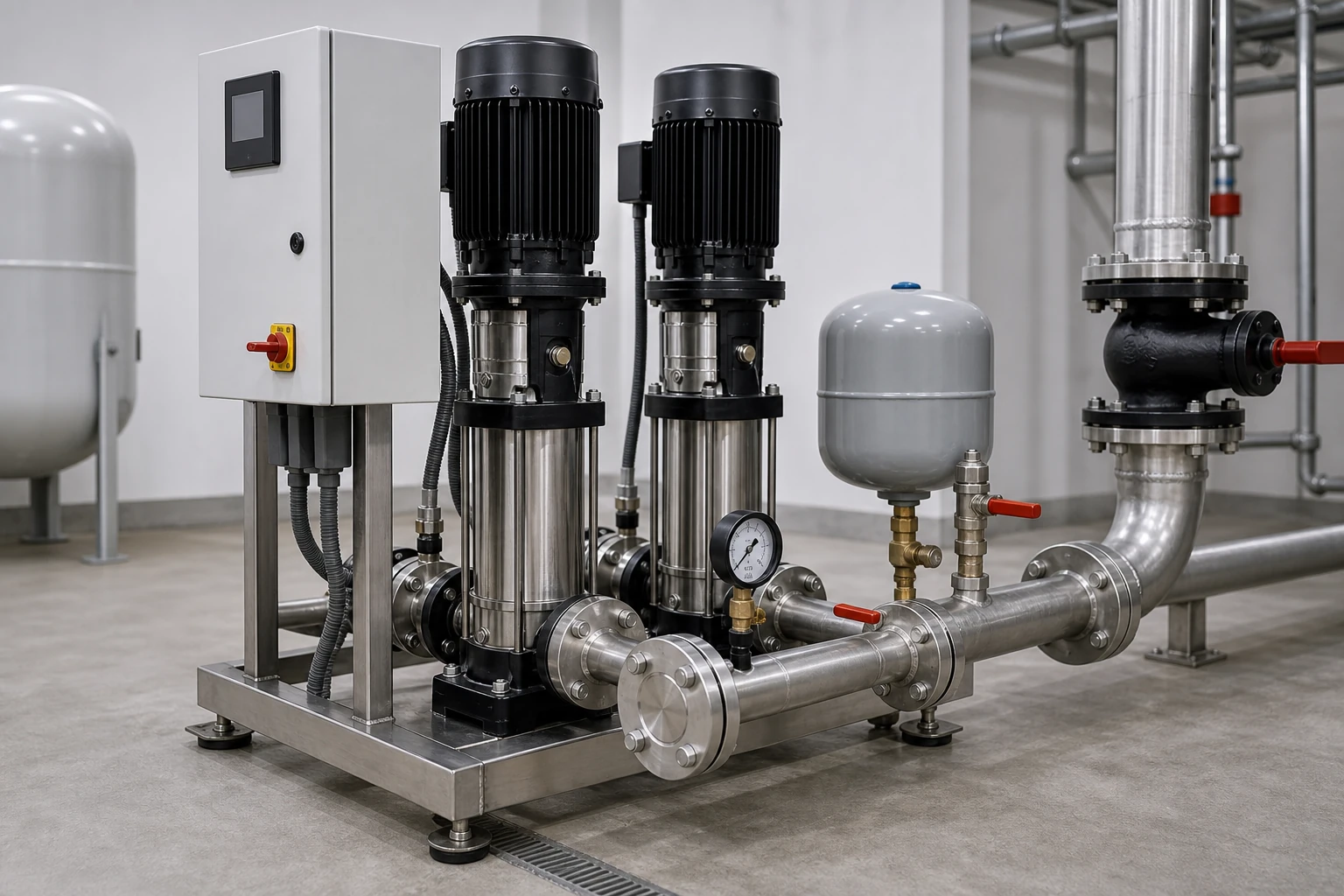
Astuce : Leave clear space around the motor, controller, pressure tank and gauges before the piping is finalized.
Points de départ pertinents de Borra
- Équipement d'alimentation en eau avec régulateur et surpresseur
- Pompe d'appoint verticale multistade CDL(F)
- Pompe à eau de surpression en ligne verticale ISG Pompe à incendie
Pour un devis, veuillez communiquer le point de fonctionnement, les conditions d'origine, l'alimentation électrique, les préférences de contrôle, l'environnement d'installation ainsi que toute exigence en matière de documentation. Cela permet au fournisseur de discuter d'une solution complète sans avancer d'hypothèses non vérifiées.
Partie 6. Ce qu'il faut confirmer avant la confirmation de la commande
Before ordering equipment for booster pump installation, separate the engineering requirement from the commercial request. The engineering requirement is the actual duty point, source condition, liquid type, control method and installation environment. The commercial request is the expected supply scope, packing, lead time, documentation language and after-sales communication path. Keeping these two lists separate helps prevent a low-price quotation from hiding missing accessories or missing documents.
Demandez au fournisseur d'indiquer le modèle de pompe sélectionné, la disposition de l'entraînement ou du moteur, l'étendue du contrôleur, les principaux accessoires, la taille des raccordements, les hypothèses de matériaux, les documents de test et les éléments exclus de la fourniture. Si un dessin est fourni, vérifiez s'il s'agit uniquement d'un plan d'implantation conceptuel, d'un dessin d'ensemble ou d'un document spécifique au projet. Cette distinction est importante car les acheteurs confondent souvent une simple image d'implantation avec un dessin d'installation final.
Pour les projets de remplacement ou de modernisation, incluez des photos de la pompe existante, de la plaque signalétique, des manomètres, de la direction des tuyaux, du réservoir, du contrôleur et de l'espace au sol disponible. Pour les nouveaux projets, incluez le débit de conception, le mode de fonctionnement prévu et toutes les contraintes du site telles que l'altitude, la température ambiante, la disponibilité de l'énergie, le drainage, la voie d'accès et les limites de bruit. Ces détails réduisent les cycles de révision et aident le fournisseur à recommander un ensemble pratique plutôt qu'une pompe générique.
Astuce : Si l'acheteur ne peut pas fournir un cahier des charges complet, marquez l'offre comme préliminaire et listez clairement les données manquantes dans les notes du devis.
FAQ
Où faut-il installer une pompe de surpression ?
Install it after a stable water source and before the distribution line that needs higher pressure, with isolation valves and protection devices around the pump set.
Does a booster pump need a pressure tank?
Not every constant-pressure system needs a large tank, but a small tank often helps reduce short cycling, buffer small demand and stabilize control response.
Should the check valve be before or after the booster pump?
A discharge-side check valve is common to prevent reverse flow through the pump. Some projects may also require other backflow protection depending on local rules.
What data is needed for booster pump selection?
Send flow, target pressure, incoming pressure, pipe size, water source, voltage, control method, duty cycle and installation space.
Can one booster pump serve a whole building?
It can if the calculated duty point and zoning match the building demand. Larger buildings may need multiple pumps, variable speed control or pressure zones.
Why does a new booster pump short cycle?
Common causes include low demand below minimum stable flow, a mischarged tank, leaks, a narrow pressure differential or a sensor placed at the wrong point.
Can the pump be installed outdoors?
Only if the selected package, motor, controller and protection level are suitable for the outdoor environment and freeze or rain exposure is addressed.
Références
Liste de contrôle pour devis de projet
- Débit requis et pression ou hauteur cible.
- Pression d'entrée, source d'eau et condition d'aspiration.
- Milieu, température et qualité de l'eau ou teneur en matières solides.
- Alimentation, préférence de contrôleur et rapport cyclique.
- Espace d'installation, accès pour la maintenance et exigences en matière de documentation.
Contacter Borra avec les données du projet si vous avez besoin d'une discussion sur la sélection de pompes ou d'un devis d'exportation.