
An electric submersible pump diagram should make the liquid path, discharge route, cable and control relationship, source condition, and service access visible before a project team treats any equipment as a fit. It is a review aid, not a universal wiring drawing or a substitute for the actual product instructions.
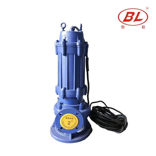
Part 1. Read the Diagram as a System Record
A useful layout begins with the job, not a product silhouette. It should show where liquid enters the system, where it leaves, what sits between those points, and who must review the electrical and service conditions. The BORRAPUMP Sewage Pump guide provides the cluster context; the diagram keeps the project-specific route visible.
| Diagram zone | What to identify | Pourquoi c'est important |
|---|---|---|
| Source | Pit, tank, sump, or other intake condition | The pump cannot be selected apart from the source |
| Pump location | Intended submerged position and access concept | Supports installation and service review |
| Décharge | Outlet, line route, fittings, and destination | Defines the liquid path |
| Electrical | Cable route and responsible control point | Separates electrical review from assumptions |
| Service | Lifting, inspection, and access notes | Avoids an unserviceable layout |
Part 2. Mark the Liquid and Discharge Path
The flow path should identify the intake condition, pump discharge connection, line route, elevation changes, fittings, and receiving point. A diagram does not need to invent flow or head values to be useful; it needs to show where the project must supply those values. The Sewage Pump Solids Handling article helps keep liquid and solids description separate from a generic product label.
| Mark on the layout | Project review question | Ne présumez pas |
|---|---|---|
| Source level and condition | Is the intake environment described? | Every pit has the same duty |
| Voie de sortie | Are length, elevation, and fittings recorded? | A straight line is the real route |
| Destination | Can the receiving point accept the liquid? | Discharge is unrestricted |
| Liquid note | Are solids, temperature, or chemistry known? | A sewage label proves compatibility |
Important : A layout should record unknowns instead of hiding them. Institut Hydraulique selection context starts with stated system conditions; confirm the exact model and project documents before installation.
Part 3. Separate Cable and Control Review From Pump Selection
An electric submersible layout can show the cable route and a control relationship, but it should never be read as a universal wiring instruction. Actual supply, protection, control logic, cable specification, and installation requirements must come from the specific product documentation and the responsible electrical review.
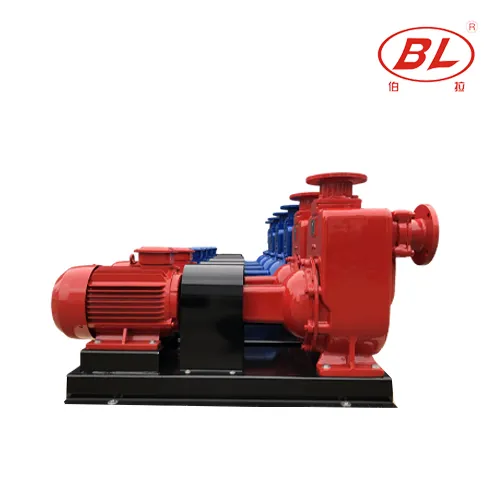
| Electrical label | Purpose in the diagram | Required confirmation |
|---|---|---|
| Cable path | Shows the physical route and protection concern | Actual cable and installation requirements |
| Control point | Shows where start/stop responsibility is reviewed | Product-specific controls and site procedure |
| Supply reference | Flags an electrical dependency | Available supply and protective arrangement |
| Alarm or level note | Flags a project interface | Actual control design and responsibility |
See Submersible vs Self-Priming Drainage Pump when access or intake conditions point to a different equipment family. Do not change pump families only because a generic diagram appears simpler.
Part 4. Add Source Conditions and Service Access
The source condition affects how the diagram is read. Mark access, lifting or removal concept, visibility, debris or solids notes, and the parts of the route that must remain accessible. A compact diagram can still make these review points explicit without pretending to be a construction drawing.
| Élément d'évaluation | Include on the record | Escalader quand |
|---|---|---|
| Accès | Working space and removal concept | Service cannot be performed safely |
| État de la source | Liquid level, debris, and known constraints | Duty is not documented |
| Line service | Isolation, check, or service notes where applicable | The line cannot be reviewed or maintained |
| Responsibility | Installer, electrical reviewer, and operator roles | Ownership is unclear |
The separate Drainage Pump Installation guide offers supporting installation questions. It does not approve an actual site layout.
Partie 5 : Transformez le diagramme en une recherche guidée
Once the diagram names the source, discharge route, liquid, access, and electrical interfaces, it can become an RFQ attachment. That gives a supplier the context needed to discuss a WQ submersible path or a self-priming alternative without replacing project data with a generic diagram.
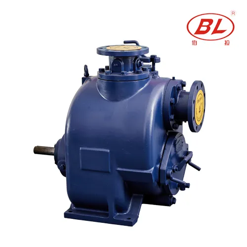
| Documented need | Itinéraire BORRAPUMP | Envoyer avec devis |
|---|---|---|
| Submerged sewage or drainage duty | WQ Submersible Sewage Pump | Source layout, liquid, flow/head basis, discharge route, power, access, destination |
| Non-clogging self-priming review | Pompe à eaux usées auto-amorçante non colmatante ZW | Intake arrangement, liquid and solids description, route, duty basis, power, destination |
| Dirty-drain route review | SP discussion after duty is documented | Debris, route, driver preference, access, destination |
Share the marked-up record with BORRAPOMPE for a controlled discussion. A generic electric submersible pump diagram is not evidence that a particular model has been selected.
Part 6. Keep the Diagram Within Its Fit Boundary
Convient pour :
- Reading the relationship between source, pump, discharge, cable, controls, and access.
- Identifying the information that must accompany a project review or inquiry.
Ne convient pas :
- Giving wiring, voltage, cable, protection, or performance instructions.
- Approving a pit, wet-well, electrical installation, or solids capability.
- Replacing the exact product manual, drawing, or responsible engineering review.
FAQ
What does an electric submersible pump diagram show?
It should show the high-level relationship between the source, pump, discharge route, cable/control interfaces, destination, and service access. The exact product documentation supplies model-specific details.
Does the diagram show the correct wiring for every pump?
No. Wiring, protection, cable details, and controls depend on the actual product and site. Use responsible electrical review and current product documentation.
What flow-path information should be marked?
Mark the source, discharge connection, route, elevation changes, fittings, receiving point, and liquid condition. Record unknown inputs instead of assuming them.
Why does the pit or source condition matter?
It affects access, liquid conditions, debris exposure, service needs, and the suitability of the proposed pump route. A pump cannot be reviewed apart from the source.
What belongs in a submersible-pump inquiry?
Send a marked-up layout, liquid description, flow/head basis, discharge route, power information, access constraints, documents required, quantity, and destination.
Can a generic diagram approve installation?
No. It is a project-review aid only. The actual installation requires site-approved documents, responsible reviewers, and the exact product instructions.
Références
- Ressources de l'Institut hydraulique for general pump-and-system selection context used when reviewing a project layout.