
A fire pump relief valve can refer to a small casing relief valve that prevents pressure buildup from heat when a pump runs at little or no flow, or a larger main pressure relief valve used only where the approved fire-protection design requires it. These devices are not interchangeable. Selection and settings must follow the adopted fire code and standard, the authority having jurisdiction, the listed equipment data, pump curve, driver behavior, and the system pressure limits. A relief valve must never be used as a casual substitute for correct pump and system design.
This guide is an early engineering and procurement framework, not a replacement for approved project design, current regulations, manufacturer instructions, or qualified site supervision. Electrical work, energized testing, lifting, confined-space entry, fire-protection work, excavation, hazardous liquids, wastewater, and pressurized systems require task-specific procedures and competent personnel. Preserve automatic protection and system availability while investigating faults. If the actual liquid, duty, site condition, or governing requirement differs from the assumptions, stop and obtain a revised technical review.
- Distinguish casing relief from main pressure relief
- Build the system pressure envelope
- Select listing, capacity, range, and discharge route
- Coordinate with pump, controller, and test arrangement
- Set, test, seal, and document the valve
- Inspect without defeating fire protection
- Table de décision
- Foire aux questions
Distinguish casing relief from main pressure relief
A casing relief valve is typically a small device connected to the pump casing or discharge arrangement to release enough water to prevent damaging temperature rise during churn or low-flow operation. It is not sized to control the full pump discharge. A main pressure relief valve, where required or permitted by the governing design, can pass a much larger flow to limit pressure under defined conditions. The project documents should name the valve type, connection, discharge destination, listing, size, pressure range, and reason for use. Confusing the two can leave a pump without thermal protection or create an unintended large discharge. Review the current adopted edition and authority comments rather than copying a detail from another project. The pump supplier should receive the system pressure basis and the fire-protection designer should approve the final arrangement.
Build the system pressure envelope
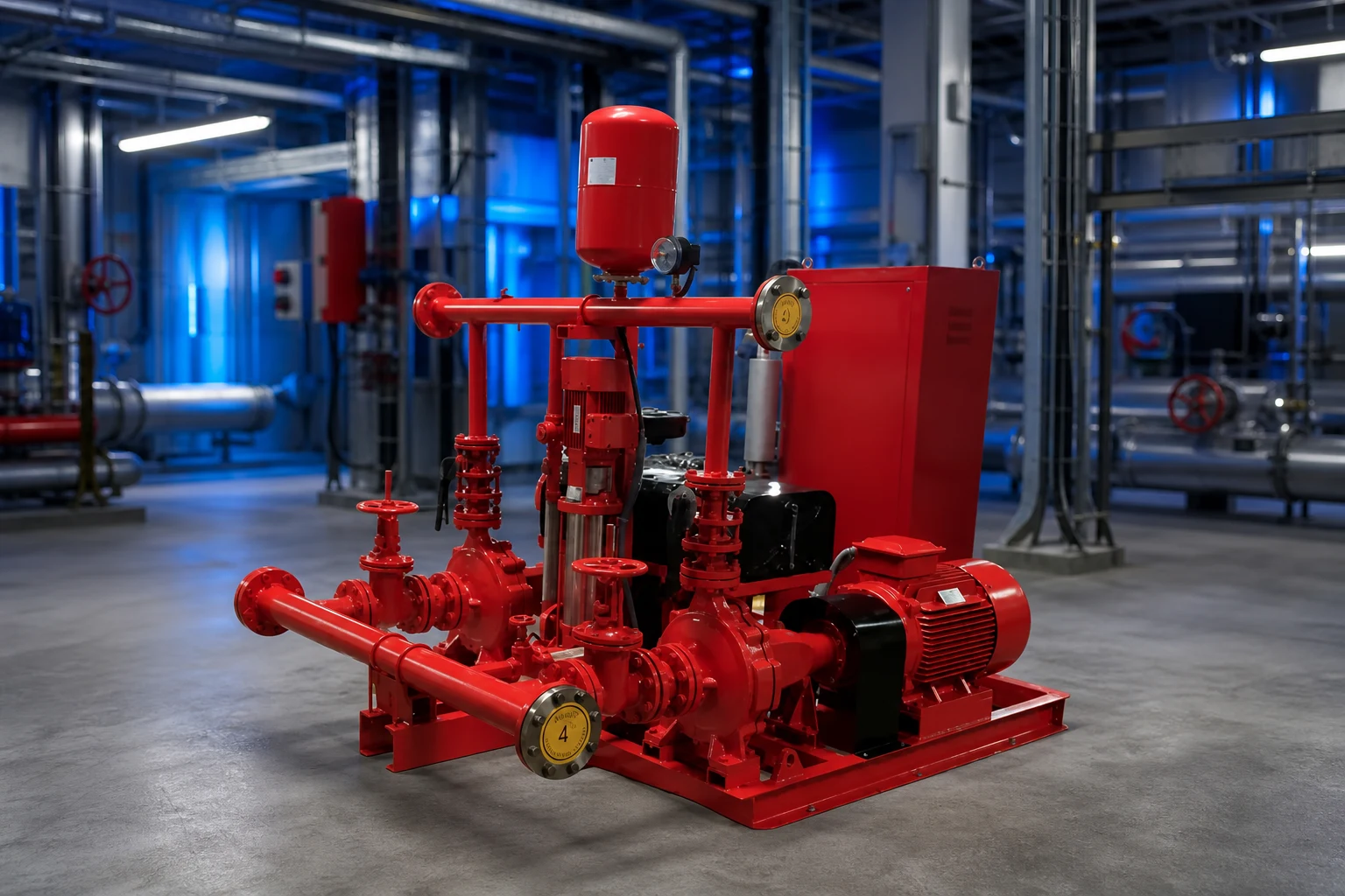
Review static suction pressure, pump rated and shutoff head, elevation, driver speed, maximum credible suction condition, test conditions, and the pressure ratings of pipe, fittings, valves, hose connections, equipment, and downstream components. For diesel-driven pumps, possible overspeed or speed variation must be addressed through the approved equipment data and design. Convert head and pressure consistently for the liquid and elevations. The relief setting cannot be chosen from the pump rated pressure alone, and it must not prevent the pump from meeting required fire-flow duty. Document normal, churn, test, and maximum credible cases. If a proposed valve setting conflicts with system ratings or required performance, resolve the pump, driver, piping, and design basis rather than treating the valve as an isolated accessory.
Select listing, capacity, range, and discharge route
Confirm that the exact valve is listed or approved as required for its fire-protection service and that size, pressure range, temperature, materials, end connections, and capacity suit the design. A main relief valve needs documented capacity at the relevant differential pressure; a casing relief valve needs the correct connection and setting range for thermal relief duty. Provide isolation only where and how the governing design allows, with supervision where required. Route discharge to a safe, visible, and acceptable location with drainage capacity, freeze protection, and protection from erosion or injury. Backpressure can affect operation and must be included when applicable. Do not discharge where water can damage electrical equipment, flood the pump room, undermine foundations, or create an unnoticed closed loop back to suction.
Table de décision du projet
| Élément d'évaluation | Casing relief valve | Main pressure relief valve |
|---|---|---|
| Primary purpose | Limit heat buildup at low or no flow | Limit system pressure where approved design requires |
| Typical flow role | Small thermal-relief flow | Larger documented relief capacity |
| Selection basis | Pump arrangement, setting range, listing | Pressure envelope, capacity, listing, backpressure |
| Discharge concern | Visible safe drain location | Full-flow route, drainage and erosion |
| Test record | Opening and reseating under approved condition | Capacity/operation under approved test method |
Coordinate with pump, controller, and test arrangement
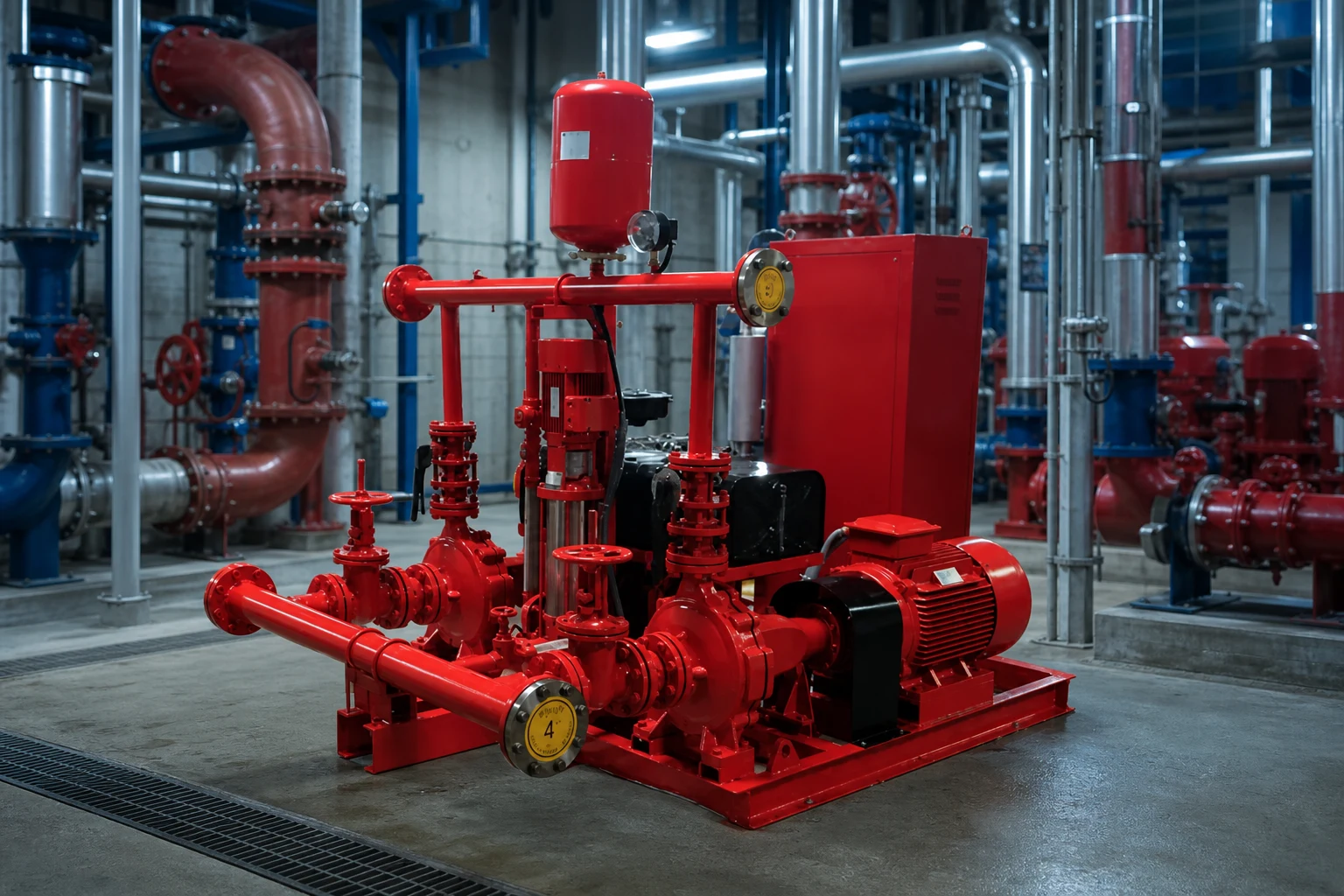
The relief valve is part of a fire pump system that includes water supply, pump, driver, controller, sensing, check and isolation valves, test header or flow meter, alarms, and room drainage. The valve arrangement must not interfere with acceptance testing or hide abnormal pump behavior. Coordinate pipe supports and valve loads with pump nozzles. The controller and alarms may need to report pump running or other conditions, but a mechanical relief valve should not be assumed to correct control settings. Review whether a variable-speed pressure-limiting control strategy is used and how its required backup and failure behavior are addressed by the approved design. Every device and set point should appear consistently on drawings, calculations, schedules, and test procedures.
Set, test, seal, and document the valve
Settings should be established by qualified personnel using calibrated instruments and the approved procedure. Record the valve identification, model, size, listed range, final setting, gauge identification, pump speed, suction pressure, discharge pressure, flow condition, discharge observation, and authority or responsible-party acceptance. Test casing relief operation under the applicable low-flow condition without allowing unsafe temperature rise. Test a main relief valve only through the approved method and with a discharge route capable of handling the flow. After adjustment, secure and seal the device as required and update the record. Never raise a setting merely to stop nuisance discharge until the cause—incorrect setting, high suction pressure, speed, blocked discharge, backpressure, or system mismatch—has been identified.
Inspect without defeating fire protection
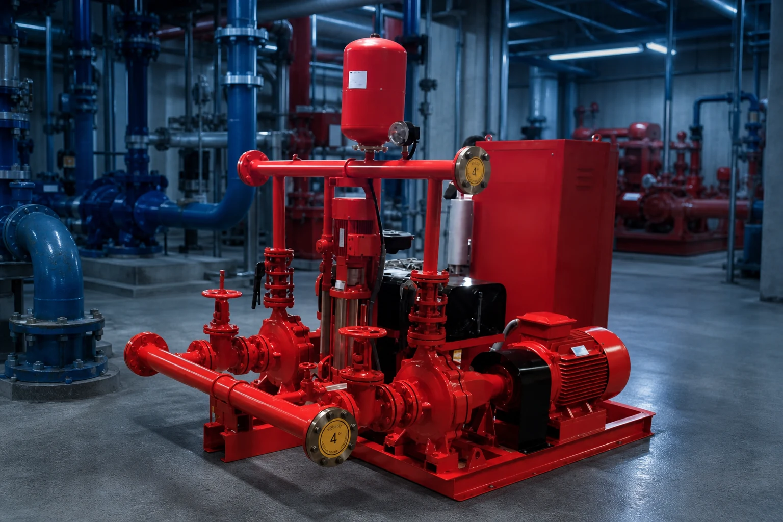
Inspection should look for leakage, corrosion, damage, blocked outlets, closed or improperly positioned valves, missing seals, changed settings, unsafe discharge, freeze exposure, and evidence of repeated operation. Maintenance frequency and test scope follow the adopted requirements, manufacturer instructions, impairment procedure, and facility program. Before isolating or servicing any fire-protection component, follow the approved impairment and notification process. Replacement is not complete until the listing, size, range, setting, discharge, and system record are verified. A relief valve that is silent may still be blocked or isolated, while one that leaks may be warning of system pressure changes. Trend observations with pump test results rather than treating the valve as a standalone plumbing item.
Procurement and acceptance record
A complete supplier comparison should use one common data sheet. Put the design and alternate duty points, liquid, temperature, solids, site elevation, power, controls, installation, operating hours, quantity, destination, and required documents at the top. Normalize differences in scope before comparing price or efficiency. Request a certified curve or capacity data, absorbed power, operating limits, materials, dimensions, weight, connections, motor or driver, controller, accessories, tests, preservation, spare parts, installation instructions, and warranty boundary. Record every deviation and unresolved assumption. During technical review, trace each offered feature back to a project input instead of awarding points for features that the duty does not need. During commissioning, measure the same variables used for selection so the installed result can be compared with the original basis. If field conditions differ, update the calculation and obtain responsible approval before changing equipment or protection settings.
How this topic connects to BORRAPUMP equipment
This guide supports early review of the fire pump relief valve application route. It does not assign a final model or claim that one standard configuration fits every project. Send the duty points, liquid data, site drawing, power supply, controls, quantity, destination, required approvals, and inspection scope so the proposed product can be checked against the real service.
Guides d'ingénierie BORRAPUMP associés
- Bases de la conception des systèmes de pompes incendie
- NFPA 20 fire pump acceptance testing
- schéma du système de pompe à incendie
Sources officielles et pour aller plus loin
NFPA fire pumps topic; OSHA fire protection; FM Global resources. These sources provide general safety, environmental, or engineering context. The current adopted rules, project approvals, and equipment instructions remain controlling.

Educational video by Practical Engineering: Do Pumps Create Pressure or Flow?. Il expose des principes de base et ne remplace pas les instructions spécifiques au projet.
Foire aux questions
Is a casing relief valve the same as a main relief valve?
No. The casing valve normally provides small thermal-relief flow; a main pressure relief valve has a different system-pressure and capacity role.
Can a relief valve fix an oversized fire pump?
It should not be used as a casual substitute for correct pump, driver, and system design. The approved fire-protection designer and authority must review the pressure basis.
Where should relief water discharge?
To the safe, visible, code-compliant location shown by the approved design, with adequate drainage, freeze protection, and no hazard to equipment or people.
Who can change the setting?
Only qualified authorized personnel following the approved procedure, with calibrated instruments and updated test records.
Final project checkpoint
Before order placement or field change, reconcile the approved duty and drawings with the supplier data, materials, dimensions, weights, connections, driver, controls, accessories, protection, test scope, documentation, spare parts, installation method, maintenance access, and destination requirements. Record remaining assumptions and assign responsibility for closing them. The final accepted information should be the same basis used for installation, commissioning, and future maintenance.