
A jockey pump controller automatically starts and stops the pressure-maintenance pump so small leaks and normal pressure loss do not start the main fire pump. Its settings must coordinate with the fire pump controller, pressure-sensing line, pump curve, system pressure, and adopted fire-protection requirements. The jockey pump should start before the main fire pump and stop after pressure recovers, while the main fire pump's automatic-start behavior remains protected. Final settings and wiring require the approved design, listed controller data, responsible engineer, and authority having jurisdiction.
This guide is an early engineering and procurement framework, not a replacement for approved project design, current regulations, manufacturer instructions, or qualified site supervision. Electrical work, energized testing, lifting, confined-space entry, fire-protection work, excavation, hazardous liquids, wastewater, and pressurized systems require task-specific procedures and competent personnel. Preserve automatic protection and system availability while investigating faults. If the actual liquid, duty, site condition, or governing requirement differs from the assumptions, stop and obtain a revised technical review.
Understand the pressure-maintenance sequence
The jockey pump handles small leakage and pressure decay, not the design fire flow. When system pressure falls to its start setting, the controller starts the jockey pump. After pressure rises to the stop setting and any permitted timing condition is satisfied, it stops. If pressure continues to fall because demand exceeds jockey capacity or the jockey pump fails, the main fire pump controller starts at its lower pressure threshold according to the approved sequence. The main fire pump normally requires manual stop unless the adopted design specifically permits another arrangement. Write the sequence in plain language and show every pressure threshold on one schedule. Avoid overlapping or reversed settings that cause simultaneous starts, short cycling, or delayed main-pump response. Settings should reflect actual static and churn pressures, elevation, and calibrated field readings.
Coordinate pressure settings and sensing
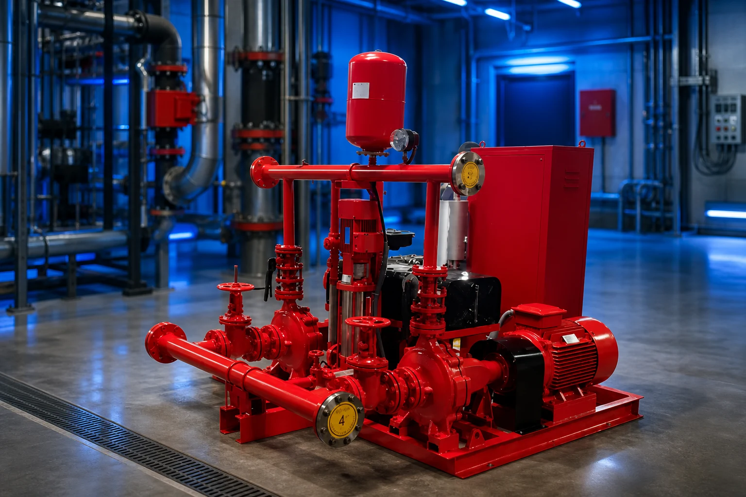
Develop a pressure envelope that includes normal static pressure, minimum expected supply, jockey pump shutoff and operating pressure, fire pump start pressure, pump churn pressure, elevation zones, and equipment ratings. The jockey stop point must be achievable without exceeding component limits, while its start point needs enough separation to avoid rapid cycling. The fire pump start point must remain below the jockey start point with the approved differential. Pressure-sensing lines need the required connection point, valves, restrictions, drainage, and protection from freezing, blockage, vibration, and mechanical damage. Do not share or alter sensing arrangements casually. Use calibrated gauges at the controller and an appropriate reference point, and investigate persistent differences before changing settings.
Select controller and motor protection
Confirm controller voltage, phase, frequency, motor full-load current, starting method, enclosure, short-circuit rating, disconnect and overcurrent arrangement, alarms, remote contacts, and required listing or approval. The controller must suit the jockey pump motor and the environment, including temperature, moisture, dust, corrosion, and hazardous classification where applicable. Review overload behavior carefully: it should protect the jockey motor without compromising the approved fire system sequence. Define hand, off, and automatic modes and who is authorized to use them. Remote monitoring can report run, failure, power, or pressure conditions, but it should not introduce an unapproved remote stop. Wiring diagrams, terminal schedules, cable sizes, grounding, and interface responsibilities should be coordinated before installation.
Table de décision du projet
| Controller item | What to verify | Why it matters |
|---|---|---|
| Jockey start pressure | Above main fire pump start setting | Handles small losses first |
| Jockey stop pressure | Achievable and within system ratings | Restores pressure without continuous run |
| Pressure sensing line | Correct source, valves and clear path | Gives reliable automatic response |
| Motor/controller data | Voltage, phase, current, enclosure, listing | Protects motor and preserves compliance |
| Cycle log | Starts, runtime and pressure trend | Reveals leakage or control drift |
| Sequence test | Jockey then main pump at separate points | Confirms coordinated protection |
Prevent short cycling and hidden leakage
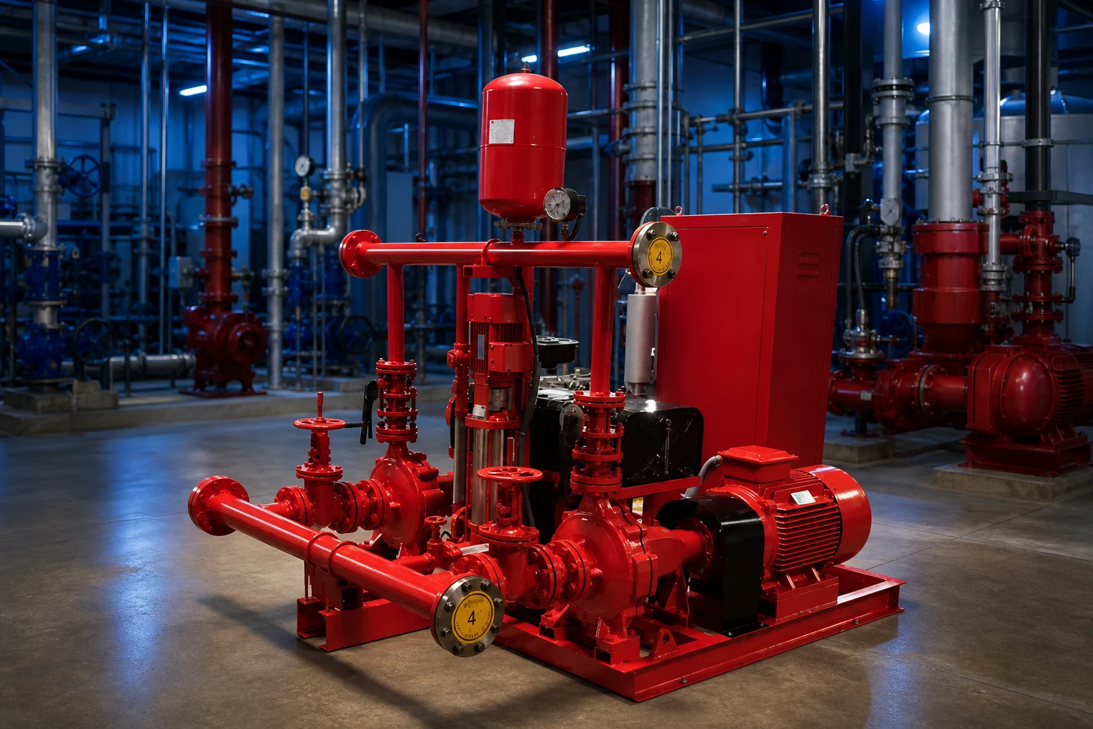
Frequent starts can indicate settings too close together, insufficient pressure-maintenance volume, a leaking check valve, sprinkler-system leakage, sensing-line trouble, trapped air, pressure-zone interaction, or an undersized jockey pump. Do not widen settings until the cause is understood. Record starts and runtime, then inspect the system at the same time each day to identify patterns. A jockey pump that runs continuously may be unable to reach stop pressure, may have lost prime, may be rotating incorrectly, or may be facing an open path. A controller that never starts could have a blocked sensing line, wrong mode, failed input, incorrect calibration, or genuinely stable pressure. Troubleshooting must protect the main fire pump's automatic readiness and follow the facility impairment procedure.
Commission the complete sequence
Verify controller identification, power, grounding, motor data, phase sequence, pump readiness, valve positions, sensing line, gauge calibration, mode, and alarm connections. Reduce pressure through the approved test connection and record the exact jockey start pressure, running pressure, stop pressure, stop delay where applicable, current, voltage, run time, and pressure recovery. Continue the approved test to demonstrate main fire pump automatic start at its separate threshold without disabling protection. Test power loss, controller alarm, remote signal, lead-lag or multiple-zone behavior where provided, and restoration to normal automatic service. Compare results with drawings and set-point schedules. Seal or protect adjustments as required and leave a dated record in the pump room and maintenance system.
Maintain records and control changes
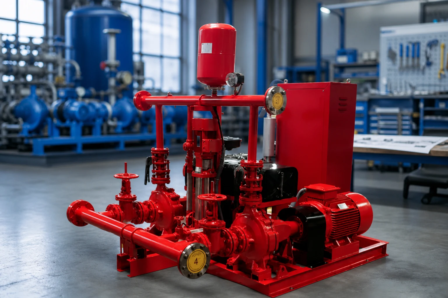
Routine review should include controller power, automatic mode, pressure indication, alarms, unusual starts, contactor condition, enclosure, ventilation, sensing line, drains, and signs of moisture or corrosion. Maintenance intervals follow the controller instructions and adopted inspection program. Record every setting change with the reason, approving person, before and after values, instrument, and functional-test result. Renovations, pressure-zone changes, water-supply changes, pump replacement, or controller updates can invalidate old settings. Never treat a nuisance main-pump start as justification to lower sensitivity without an engineering review. The log of pressure and jockey cycles is valuable evidence of system leakage or changing supply conditions when it is kept consistently.
Procurement and acceptance record
A complete supplier comparison should use one common data sheet. Put the design and alternate duty points, liquid, temperature, solids, site elevation, power, controls, installation, operating hours, quantity, destination, and required documents at the top. Normalize differences in scope before comparing price or efficiency. Request a certified curve or capacity data, absorbed power, operating limits, materials, dimensions, weight, connections, motor or driver, controller, accessories, tests, preservation, spare parts, installation instructions, and warranty boundary. Record every deviation and unresolved assumption. During technical review, trace each offered feature back to a project input instead of awarding points for features that the duty does not need. During commissioning, measure the same variables used for selection so the installed result can be compared with the original basis. If field conditions differ, update the calculation and obtain responsible approval before changing equipment or protection settings.
How this topic connects to BORRAPUMP equipment
This guide supports early review of the jockey pump controller application route. It does not assign a final model or claim that one standard configuration fits every project. Send the duty points, liquid data, site drawing, power supply, controls, quantity, destination, required approvals, and inspection scope so the proposed product can be checked against the real service.
Guides d'ingénierie BORRAPUMP associés
Sources officielles et pour aller plus loin
NFPA fire pumps topic; OSHA electrical safety; OSHA control of hazardous energy. These sources provide general safety, environmental, or engineering context. The current adopted rules, project approvals, and equipment instructions remain controlling.
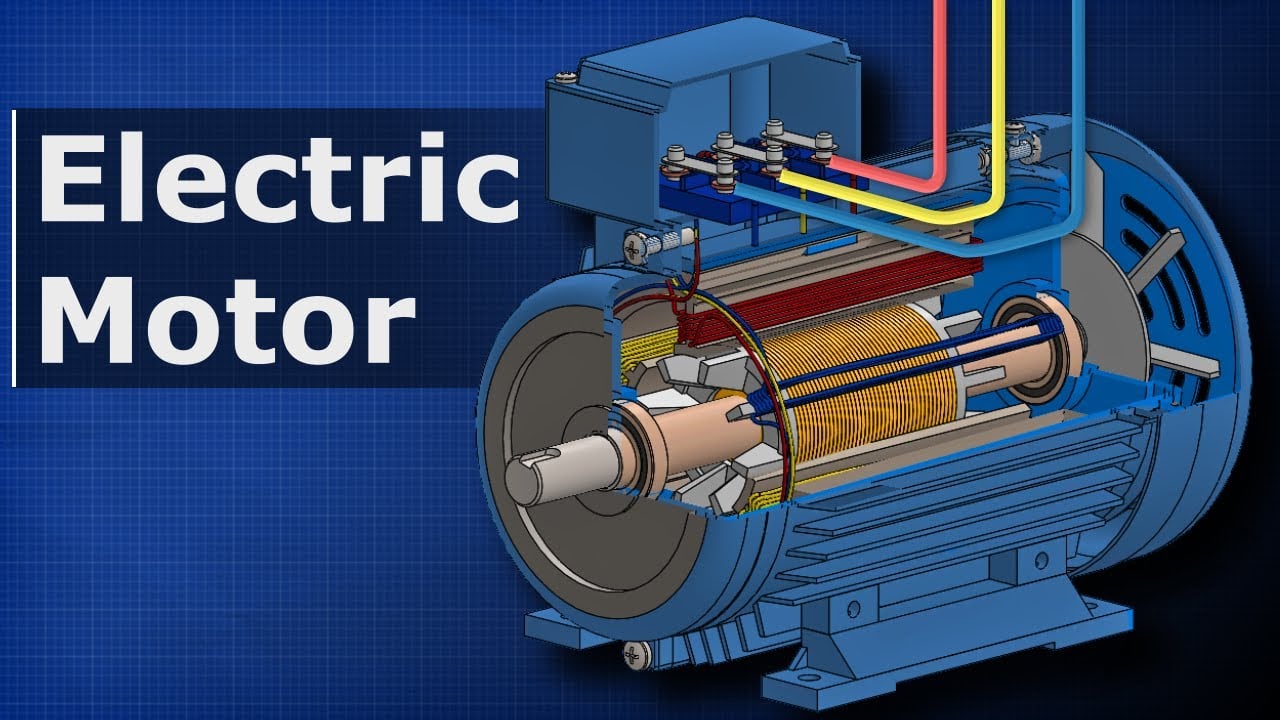
Educational video by The Engineering Mindset: How Electric Motors Work: Three-Phase AC Induction Motors. Il expose des principes de base et ne remplace pas les instructions spécifiques au projet.
Foire aux questions
What does a jockey pump controller do?
It starts and stops the pressure-maintenance pump to restore small pressure losses without starting the main fire pump.
Should the jockey pump start before the fire pump?
Yes, the approved settings normally place jockey start above the main fire pump start threshold with adequate separation.
Why is the jockey pump cycling frequently?
Possible causes include leakage, check-valve trouble, narrow settings, low system volume, sensing problems, trapped air, or insufficient pump capacity.
Can the controller stop the main fire pump automatically?
Do not assume so. Main fire pump stopping follows the adopted requirements and approved controller arrangement, commonly requiring manual action.
Final project checkpoint
Before order placement or field change, reconcile the approved duty and drawings with the supplier data, materials, dimensions, weights, connections, driver, controls, accessories, protection, test scope, documentation, spare parts, installation method, maintenance access, and destination requirements. Record remaining assumptions and assign responsibility for closing them. The final accepted information should be the same basis used for installation, commissioning, and future maintenance.