
Submersible pump cable sizing requires more than matching a motor’s power to a wire-size table. The selected cable must carry the design current under the actual installation conditions, keep operating and starting voltage acceptable, suit immersion and handling, fit the terminals and work with the protective devices. Calculate the complete supply route, including any surface feeder and extension. Use the motor’s specified current and starting arrangement, not an assumed current derived only from kilowatts. A qualified electrical designer should confirm the final selection against the equipment instructions and applicable installation rules.
Define the complete circuit before choosing a cable
Draw the route from the source to the motor. Identify the surface feeder, control panel, drop cable, joints, connectors and any temporary extension. Record the one-way length of each section and the method of installation. A long feeder before the controller still contributes to the voltage available at the pump, even if the submersible cable itself is relatively short.
Identify whether the supply is single-phase or three-phase and whether the motor is started directly, through another starting arrangement or by a variable-speed drive. Record the actual motor voltage and current from the supplied documentation. For a BorraPumps WQ sewage pump, confirm the cable and controls supplied for that unit. Do not infer them from a family-level product photograph.
Separate current capacity from voltage drop
Current capacity addresses the cable’s ability to carry the required load without exceeding the permitted temperature under the installed conditions. Voltage drop addresses how much the supply voltage changes along the circuit. These are separate checks. A cable that passes an ampacity check can still leave inadequate voltage at a distant motor, while a voltage-drop calculation does not establish that the cable installation is thermally acceptable.
Use the applicable tables and correction factors for the cable type, conductor material, installation method, ambient conditions and grouping. A cable in free air, an enclosed route and a grouped tray can have different requirements. Include the relevant conditions for the immersed section and any section exposed to warmer air. Do not apply a free-air rating to the entire route merely because part of the cable is visible.
Use the motor data that matches the supplied configuration
Collect the rated voltage, phase, frequency, rated current, starting method and the permitted supply conditions. Also obtain the requirements for protective earth, thermal devices, moisture monitoring and any separate sensor circuits. The cable serving a motor power circuit may have a different purpose from the small conductors serving a monitoring device. Keep them identified in the design records.
Le DOE motor and drive system sourcebook explains the importance of matching motors with their electrical and operating conditions. Use that system perspective when reviewing cable selection. A replacement with the same nominal power can still differ in current, starting behavior, terminals or supply requirements.
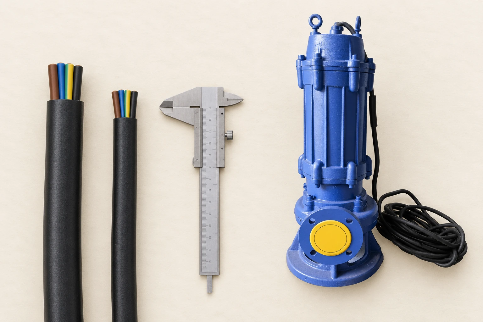
Calculate running voltage drop transparently
For a balanced three-phase circuit, a commonly used approximate calculation is ΔV = √3 × I × L × (R cos φ + X sin φ). Here ΔV is line-to-line voltage drop in volts, I is line current in amperes, L is the one-way route length in kilometres, and R and X are the conductor resistance and reactance in ohms per kilometre under the relevant conditions. The power factor is cos φ. Use consistent units and data appropriate to the selected cable.
This expression is a design estimate for its stated circuit assumptions, not a substitute for the applicable installation method or a detailed drive-system review. Do not use it unchanged for a single-phase circuit. Resistance changes with conductor temperature, and the values used should match the intended calculation conditions. The designer should establish which effects are significant for the route and supply arrangement.
A worked example with explicit assumptions
Consider an illustrative balanced three-phase circuit at 400 V carrying 20 A over a one-way length of 0.15 km. Assume the selected calculation data are R = 1.5 Ω/km, X = 0.08 Ω/km and a power factor of 0.85, giving sin φ approximately 0.527. These are example inputs, not the specification of a BorraPumps motor or a recommended cable size.
The estimated drop is √3 × 20 × 0.15 × [(1.5 × 0.85) + (0.08 × 0.527)], or approximately 6.84 V. Relative to 400 V, this is about 1.71%. This result describes only the section and operating case included in the calculation. It does not establish compliance or acceptable starting voltage. Add the upstream route and use the project’s actual supply and acceptance criteria before choosing the cable.
Review motor starting as a separate case
Starting current and power factor can differ from the running values. The source voltage can also change under a starting load, especially when a generator or a limited supply is used. A calculation based only on rated running current can therefore miss the condition that determines whether the motor accelerates successfully.
Obtain the starting data for the selected motor and starter. Review the source, feeder and motor as a complete circuit for the intended start. Avoid using an arbitrary current multiplier as a guaranteed design value. Where a drive is installed, follow the drive and motor instructions for cable length, cable construction, output filtering and electromagnetic compatibility rather than treating the arrangement as an ordinary fixed-frequency feeder.
Use a selection checklist that separates the checks
| Vérifier | Required input | What must be confirmed |
|---|---|---|
| Current capacity | Motor current, cable type and installation conditions | Applicable ratings and correction factors |
| Running voltage | Full route, conductor data and running load | Motor-terminal conditions within the permitted range |
| Starting voltage | Motor starting data and source behavior | Acceptable acceleration and starting conditions |
| Immersion and environment | Liquid, depth, temperature and handling | Cable and joint suitability |
| Protection and termination | Protective devices, earth conductor and terminals | Coordination and physical compatibility |
The table is a design workflow. It does not replace the local electrical rules or provide a universal wire size for a particular pump power.

Specify immersion, joints and mechanical protection
Confirm that the cable, glands, connectors and joints are suitable for the intended environment. Water exposure is not the only consideration: chemical contamination, temperature, movement, abrasion and strain can also matter. Record the conditions expected during installation, operation and retrieval. A cable supplied for one environment should not be assumed suitable for every wastewater composition or installation depth.
Locate joints and plan their access and inspection. Avoid an extension arrangement that introduces an unsuitable connection into an immersed or frequently flooded area. Provide the support required by the equipment instructions, and keep lifting forces off the cable. The guide rail installation review is a related mechanical-access check, while cable routing remains a separate electrical design item.
Check protection and terminal compatibility
The final cable choice must work with the protective arrangement and the required disconnection conditions. Confirm the protective earth conductor and the manufacturer’s termination requirements. A larger conductor is not automatically usable if the terminal cannot accept it or if the bend radius and gland arrangement become unsuitable. Resolve these physical interfaces before ordering.
Document the protection settings and the basis for the selection. Do not change a protective-device setting merely to hide a starting problem or a recurring trip. Investigate the circuit, motor and operating condition first. The HSE electrical inspection and testing guidance points to the need for competent testing and appropriate precautions when verifying electrical equipment.
Verify the installation and keep a baseline
Before service, complete the prescribed installation checks using qualified personnel. Record the actual cable lengths and identification, joints, terminations and protective settings. Where measurements are taken, keep the operating condition with the readings so that a later comparison is meaningful. A voltage measured at an unloaded panel does not establish the voltage available at the loaded motor.
Use the guide de maintenance des pompes submersibles for the continuing inspection record. When an insulation check is required, use the separate insulation resistance testing guide after that scheduled page becomes available. Cable sizing, insulation condition and motor cooling address different questions; record their results separately.
Prepare a complete procurement request
Send the electrical designer or supplier the motor data, route drawing, section lengths, source arrangement, starter or drive details, environment and local requirements. State whether the cable is supplied with the pump or purchased separately. Request the assumptions, calculation cases and installation limitations with the proposed size rather than accepting a conductor designation without its basis.
For a replacement installation, include the original cable condition and fault history. If the route has been extended or the power source changed, recalculate the circuit. Retaining the old size because the replacement motor has the same power can overlook the change that caused poor starting or unacceptable voltage. Preserve the approved design with the asset record for future modifications.
Learning resource
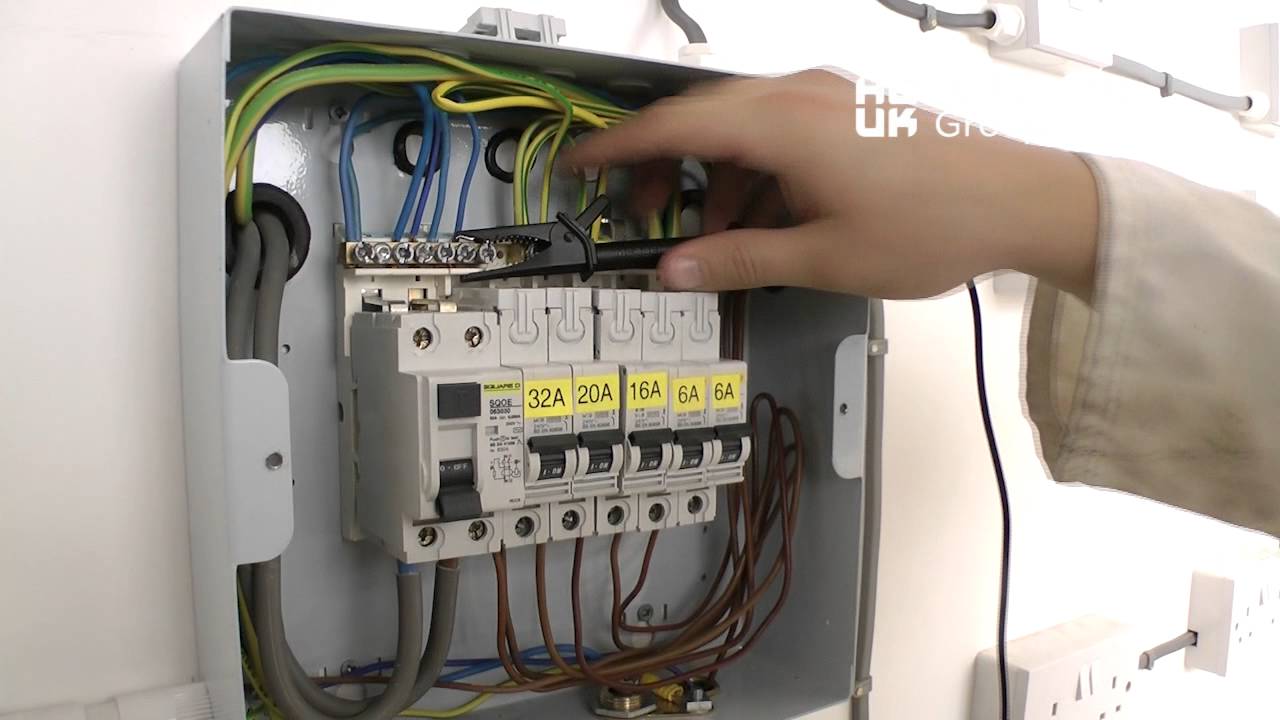
Hull College’s electrical insulation-testing demonstration illustrates one part of checking an electrical installation. It complements the commissioning discussion; it is not a cable-sizing table or a submersible motor connection instruction.
Foire aux questions
Can cable size be selected from motor kilowatts alone?
No. Use the actual motor current, supply, route, installation conditions, starting arrangement, environment and protection requirements.
Does passing the current-capacity check prove voltage drop is acceptable?
No. Calculate voltage conditions separately for the complete route and the relevant running and starting cases.
Is cable length the one-way length in the three-phase example?
Yes. The example uses one-way route length in kilometres and conductor resistance and reactance in ohms per kilometre.
Should an existing cable be reused after a pump replacement?
Only after its condition and suitability for the replacement configuration are verified. Recheck changes in current, starting method, route and environment.