
When a fire pump test fails, preserve system readiness first, then diagnose from evidence: confirm instruments, pump speed, suction supply, valve position, test arrangement, driver condition, and the accepted baseline before opening the pump or changing settings. A low discharge reading can come from low suction pressure, gauge error, reduced speed, a bypass path, air, obstruction, wear, or an incorrect test setup. Record the failed point and manage any impairment under the approved procedure. Keep the calculation and acceptance record with the final project documents so future tests use the same basis.
Keamanan dan cakupan: Pompa pemadam kebakaran dan penggeraknya adalah peralatan keselamatan jiwa. Pekerjaan hidrolik, kelistrikan, diesel, bahan bakar, baterai, tekanan, peralatan berputar, pengujian, dan gangguan harus mengikuti desain disetujui saat ini, instruksi pabrikan, standar yang berlaku, dan otoritas yang memiliki yurisdiksi. Panduan ini menjelaskan jalur keputusan teknik; panduan ini tidak mengizinkan perubahan lapangan, pengoperasian bypass, atau pengoperasian oleh personel yang не berkualifikasi.
Define exactly what failed
State the test point, expected basis, measured flow, suction and discharge pressure, speed, alarms, duration, and acceptance criterion. Treat this as a system condition rather than an isolated component choice. Identify the source of every input, the unit used, the operating condition it represents, and the person responsible for approval. If information is preliminary, mark the assumption and test how the decision changes at a conservative boundary. This prevents a neat calculation from hiding an uncertain water level, pressure, valve position, driver condition, or simultaneous demand.
For fire pump test failure, verify this section against the selected pump curve, the actual site arrangement, manufacturer instructions, and the current requirements accepted by the authority having jurisdiction. Check the installed condition as well as the drawing because pipe routes, elevations, supports, controls, and access often change during construction. Record the result in a form that can be repeated during commissioning and later inspection. Do not change a safety-critical setting or isolate fire protection without the approved impairment and restoration process.
Protect the fire system
Notify responsible parties, keep available protection in service, and use the approved impairment process if the pump or water supply cannot meet its duty. The most useful evidence is measured or approved project data, not a copied rule of thumb. Identify the source of every input, the unit used, the operating condition it represents, and the person responsible for approval. If information is preliminary, mark the assumption and test how the decision changes at a conservative boundary. This prevents a neat calculation from hiding an uncertain water level, pressure, valve position, driver condition, or simultaneous demand.
For fire pump test failure, verify this section against the selected pump curve, the actual site arrangement, manufacturer instructions, and the current requirements accepted by the authority having jurisdiction. Check the installed condition as well as the drawing because pipe routes, elevations, supports, controls, and access often change during construction. Record the result in a form that can be repeated during commissioning and later inspection. Do not change a safety-critical setting or isolate fire protection without the approved impairment and restoration process.
Verify instruments first
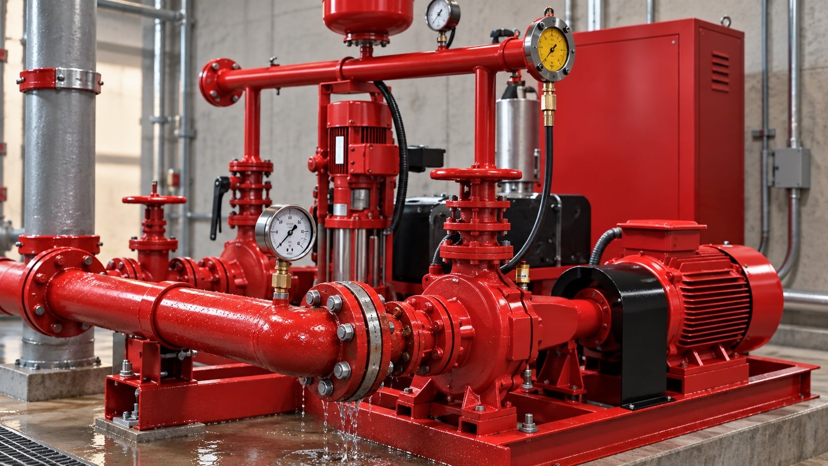
Check gauge range, calibration, zero, hose or meter condition, flow-measurement method, and data transcription before blaming the equipment. Review this condition at normal, test, and credible abnormal states before procurement. Identify the source of every input, the unit used, the operating condition it represents, and the person responsible for approval. If information is preliminary, mark the assumption and test how the decision changes at a conservative boundary. This prevents a neat calculation from hiding an uncertain water level, pressure, valve position, driver condition, or simultaneous demand.
For fire pump test failure, verify this section against the selected pump curve, the actual site arrangement, manufacturer instructions, and the current requirements accepted by the authority having jurisdiction. Check the installed condition as well as the drawing because pipe routes, elevations, supports, controls, and access often change during construction. Record the result in a form that can be repeated during commissioning and later inspection. Do not change a safety-critical setting or isolate fire protection without the approved impairment and restoration process.
Confirm source and valve arrangement
Review tank level, municipal pressure, suction obstruction, valve indication, check valves, test return, bypass, and unintended discharge paths. The design team should turn this point into a traceable calculation or drawing note. Identify the source of every input, the unit used, the operating condition it represents, and the person responsible for approval. If information is preliminary, mark the assumption and test how the decision changes at a conservative boundary. This prevents a neat calculation from hiding an uncertain water level, pressure, valve position, driver condition, or simultaneous demand.
For fire pump test failure, verify this section against the selected pump curve, the actual site arrangement, manufacturer instructions, and the current requirements accepted by the authority having jurisdiction. Check the installed condition as well as the drawing because pipe routes, elevations, supports, controls, and access often change during construction. Record the result in a form that can be repeated during commissioning and later inspection. Do not change a safety-critical setting or isolate fire protection without the approved impairment and restoration process.
Tabel keputusan praktis
| Failed result | Possible causes | First verification |
|---|---|---|
| Low net pressure at all flows | Low speed, wear, wrong impeller, rotation issue | Speed, curve identity, rotation |
| Normal churn, low pressure at high flow | Suction restriction or internal wear | Suction pressure and flow path |
| Unstable pressure | Air, cavitation, source disturbance | Suction route and tank level |
| High driver current or temperature | Excess flow, misalignment, rubbing | Flow point and mechanical inspection |
| Flow reading inconsistent | Meter/nozzle setup or instrument issue | Calibration and test arrangement |
| Controller alarm or failed start | Power, battery, wiring, control fault | Approved controller diagnostics |
Check driver speed and power
For electric systems, review voltage, current, phase, and frequency. For diesel, review governed speed, fuel, air, cooling, and exhaust. Treat this as a system condition rather than an isolated component choice. Identify the source of every input, the unit used, the operating condition it represents, and the person responsible for approval. If information is preliminary, mark the assumption and test how the decision changes at a conservative boundary. This prevents a neat calculation from hiding an uncertain water level, pressure, valve position, driver condition, or simultaneous demand.
For fire pump test failure, verify this section against the selected pump curve, the actual site arrangement, manufacturer instructions, and the current requirements accepted by the authority having jurisdiction. Check the installed condition as well as the drawing because pipe routes, elevations, supports, controls, and access often change during construction. Record the result in a form that can be repeated during commissioning and later inspection. Do not change a safety-critical setting or isolate fire protection without the approved impairment and restoration process.
Match the symptom to hydraulic causes
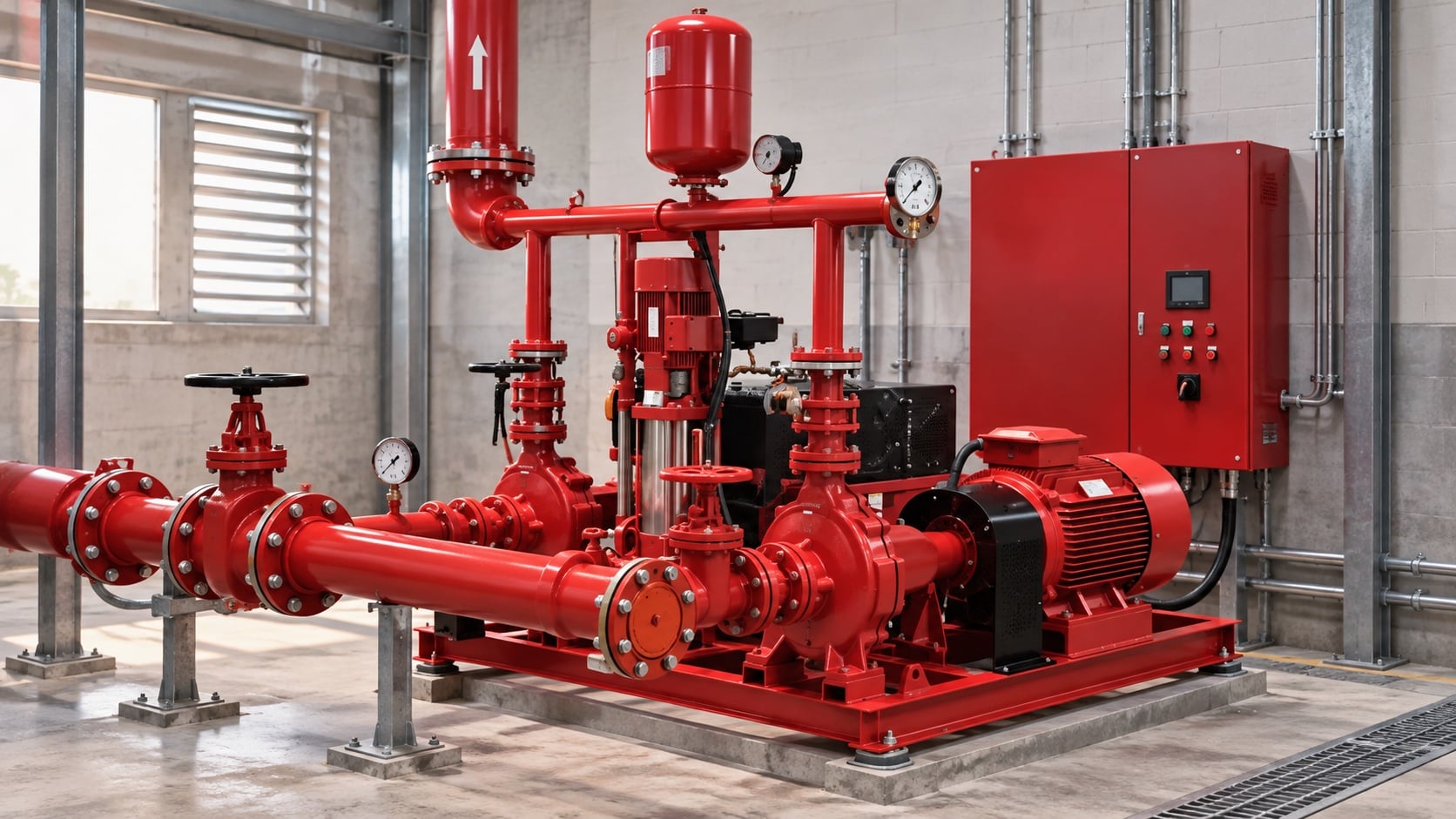
Low head, low flow, instability, high power, overheating, or vibration point to different combinations of suction, rotation, wear, blockage, and system resistance. The most useful evidence is measured or approved project data, not a copied rule of thumb. Identify the source of every input, the unit used, the operating condition it represents, and the person responsible for approval. If information is preliminary, mark the assumption and test how the decision changes at a conservative boundary. This prevents a neat calculation from hiding an uncertain water level, pressure, valve position, driver condition, or simultaneous demand.
For fire pump test failure, verify this section against the selected pump curve, the actual site arrangement, manufacturer instructions, and the current requirements accepted by the authority having jurisdiction. Check the installed condition as well as the drawing because pipe routes, elevations, supports, controls, and access often change during construction. Record the result in a form that can be repeated during commissioning and later inspection. Do not change a safety-critical setting or isolate fire protection without the approved impairment and restoration process.
Inspect mechanical condition
After safe isolation, check coupling, alignment, bearings, impeller condition, clearances, seals or packing, and evidence of rubbing or corrosion. Review this condition at normal, test, and credible abnormal states before procurement. Identify the source of every input, the unit used, the operating condition it represents, and the person responsible for approval. If information is preliminary, mark the assumption and test how the decision changes at a conservative boundary. This prevents a neat calculation from hiding an uncertain water level, pressure, valve position, driver condition, or simultaneous demand.
For fire pump test failure, verify this section against the selected pump curve, the actual site arrangement, manufacturer instructions, and the current requirements accepted by the authority having jurisdiction. Check the installed condition as well as the drawing because pipe routes, elevations, supports, controls, and access often change during construction. Record the result in a form that can be repeated during commissioning and later inspection. Do not change a safety-critical setting or isolate fire protection without the approved impairment and restoration process.
Retest and document correction
Repeat the same controlled points with calibrated instruments. Update the baseline only after the corrected result is accepted. The design team should turn this point into a traceable calculation or drawing note. Identify the source of every input, the unit used, the operating condition it represents, and the person responsible for approval. If information is preliminary, mark the assumption and test how the decision changes at a conservative boundary. This prevents a neat calculation from hiding an uncertain water level, pressure, valve position, driver condition, or simultaneous demand.
For fire pump test failure, verify this section against the selected pump curve, the actual site arrangement, manufacturer instructions, and the current requirements accepted by the authority having jurisdiction. Check the installed condition as well as the drawing because pipe routes, elevations, supports, controls, and access often change during construction. Record the result in a form that can be repeated during commissioning and later inspection. Do not change a safety-critical setting or isolate fire protection without the approved impairment and restoration process.
Bagaimana ini terkait dengan peralatan BORRAPUMP
BORRAPUMP memasok peralatan pompa rekayasa untuk proyek-proyek air dan proteksi kebakaran. Tinjau yang relevan Konfigurasi produk BORRAPUMP sebagai titik awal, lalu serahkan aliran, tinggi tekan, sumber air, penggerak, daya, kontrol, kondisi lokasi, persyaratan yang berlaku, jumlah, dan tujuan yang diperlukan. Pemilihan akhir harus menggunakan dasar hidrolik proyek dan submittal yang disetujui; panduan ini tidak mengklaim bahwa satu susunan katalog cocok untuk setiap yurisdiksi atau risiko.
Panduan BORRAPUMP terkait
- Panduan pengujian penerimaan NFPA 20
- Panduan inspeksi dan pengujian NFPA 25
- panduan paket pompa joki
Referensi otoritatif
Sumber-sumber berikut menetapkan batas standar, konteks keselamatan kebakaran, dan prinsip sistem pompa yang digunakan dalam panduan ini. Selalu terapkan edisi dan adopsi lokal yang disetujui untuk proyek tersebut.
- Halaman pengembangan standar NFPA 25
- Halaman pengembangan standar NFPA 20
- Sumber daya sistem pompa Departemen Energi AS
Video edukasi
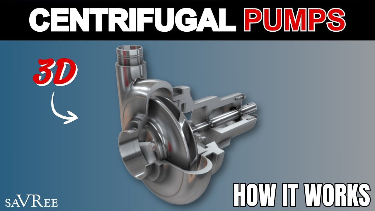
Educational background by saVRee: Cara Kerja Pompa Sentrifugal. Video tersebut mendukung konsep teknik yang mendasar dan tidak menggantikan persyaratan perlindungan kebakaran khusus proyek.
Pertanyaan yang sering diajukan
Should I adjust the pump after one failed reading?
No. Verify instruments, speed, source, valves, and repeatability before making an approved correction.
What if suction pressure changed?
Compare net pump pressure and source conditions; the discharge gauge alone can misrepresent pump performance.
Can the system remain in service after a failed test?
The responsible parties and authority must evaluate the impairment and required temporary measures under the approved process.
When should the pump be opened?
Only after external causes are checked and the unit is safely isolated under an approved inspection plan.
Daftar periksa verifikasi akhir
Sebelum persetujuan, konfirmasikan basis hidrolik, kondisi sumber air, kurva pompa yang dipilih, data penggerak dan pengontrol, peringkat tekanan komponen, susunan katup, metode pengujian, akses, drainase, alarm, dan prosedur pemulihan. Selesaikan perbedaan antara gambar kerja dan sistem yang terpasang. Selama pengujian (commissioning), gunakan instrumen yang dikalibrasi dan catat tekanan isap, tekanan buang, aliran, kecepatan, kondisi penggerak, alarm, dan pengamatan tidak normal pada setiap titik yang diperlukan. Simpan hasil yang diterima bersama catatan ruang pompa sehingga pemeriksaan selanjutnya dapat membandingkan hal yang setara.