
Choosing a self-priming pump vs a vacuum priming system is a choice about how a centrifugal pump fills its suction path and restores liquid pumping after air enters. A conventional self-priming design uses its intended retained-liquid and air-separation arrangement; a separate vacuum system evacuates air through additional equipment. Neither option removes suction losses, cavitation risk or the need for a verified duty curve. For large-flow projects, compare the complete arrangement: the suction volume, initial fill, restart behavior, air handling, controls, maintenance and acceptance test. Do not choose from maximum flow or a priming label alone.
Keep liquid pumping and air removal separate
The main pump must deliver the required water flow against the system head after priming. The priming arrangement must establish the conditions needed for that main pump to operate. These are related duties, but they are not interchangeable. A supplier can present an impressive liquid-flow curve while leaving the time and conditions required to reach that flow unresolved.
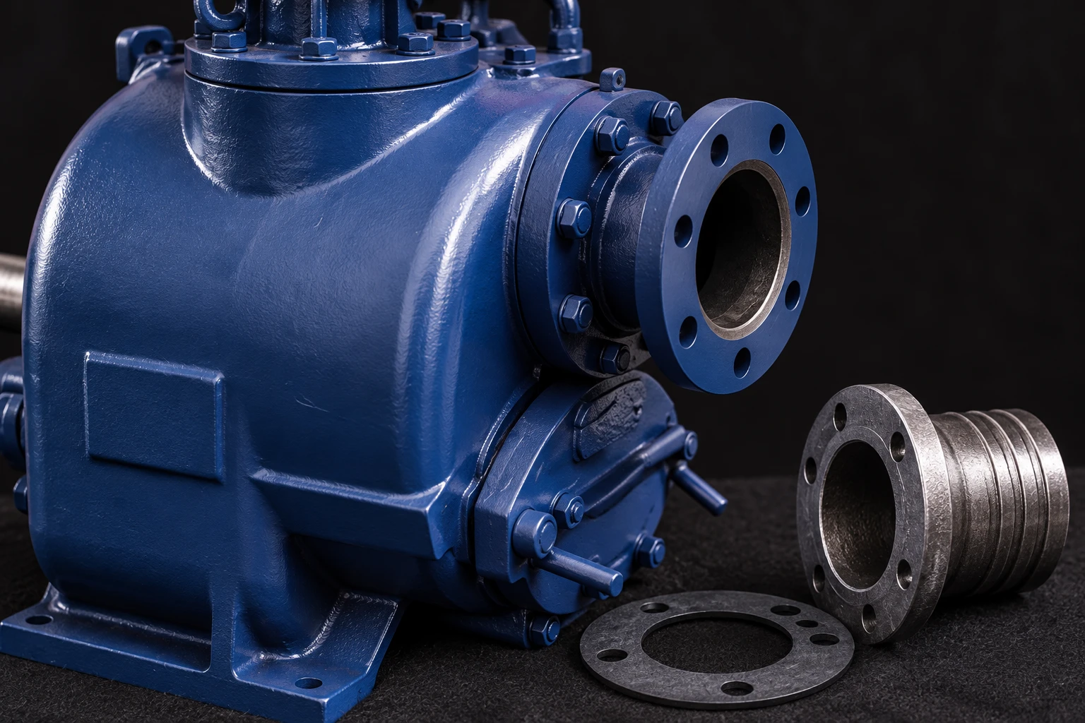
Begin with a review of the centrifugal pump curve. Confirm the specified liquid, speed, impeller configuration and operating range. Then ask for a separate explanation of the priming process. For the BorraPumps SP self-priming dirt pump, confirm the supplied assembly’s requirements rather than assuming an optional vacuum package or a particular priming capability is included.
What a conventional self-priming arrangement does
Many self-priming centrifugal arrangements use liquid retained or initially placed in the casing to work with incoming air. The exact circulation and separation paths depend on the design. The objective is to remove air from the suction line and establish a liquid supply to the impeller. The casing’s initial condition therefore matters: self-priming does not mean that every empty pump can be started dry without preparation.
Ask how the pump retains its priming liquid after shutdown, what preparation is required at first start and what inspection confirms readiness. Include the effect of a drained casing, a leaking check arrangement and a suction line that empties between cycles. Obtain limits on any operating period before stable liquid flow. Never infer a permissible dry-running time from the word self-priming.
What a separate vacuum priming arrangement adds
A separate vacuum system uses air-removal equipment and a designed connection to the water-pumping system. Depending on the supplied arrangement, it can include a vacuum pump or other evacuation device, separation equipment, valves, sensors and controls. The main water pump may then operate as a conventional centrifugal pump once the required liquid condition has been established.
Evaluate the package as a system. Ask what prevents water or solids from reaching components not designed to handle them, how the system detects completion of priming and how it behaves when air enters during operation. A vacuum-system label does not prove continuous air handling, automatic restart or compatibility with contaminated water. Those functions require explicit documentation and testing.
Compare the installation that actually needs to prime
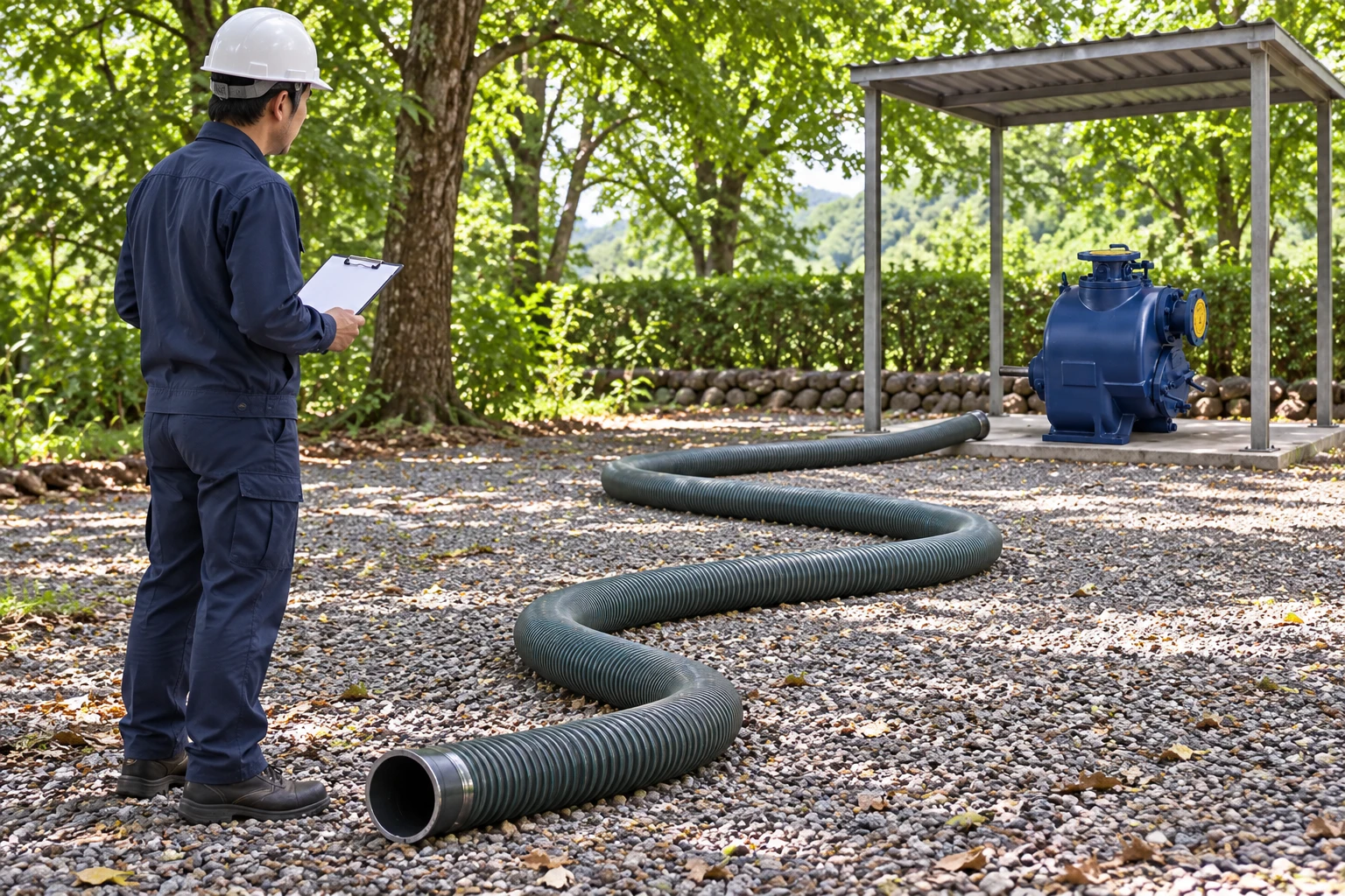
Describe the suction route, not only the nominal lift. A long route with large internal volume presents a different evacuation task from a short route at the same elevation. High points, hose deformation, submerged inlet conditions and leakage can affect the start. Determine the lowest and highest water levels and the changes expected during operation.
Prepare a sketch with elevations, lengths, internal diameters, fittings, valves and intake position. Identify which parts remain full after shutdown. Describe whether the water contains solids, foam, gas or debris. Avoid assuming that a system that primes clear water under controlled conditions will behave identically in an open excavation with changing inflow and an intermittently uncovered intake.
Use a project-specific comparison table
| Decision question | Self-priming arrangement | Separate vacuum arrangement |
|---|---|---|
| What must be prepared before first start? | Confirm casing fill and retained-liquid requirements | Confirm evacuation equipment readiness and main-pump requirements |
| What happens when the suction line empties? | Verify the documented reprime process for that line volume | Verify detection, evacuation sequence and restart permissives |
| What maintenance is added? | Check the casing, seals and specified retaining components | Include the air-removal device, separation arrangement and controls |
| How are air and liquid duties proved? | Test priming and steady pumping as distinct acceptance items | Test the vacuum package and main pump together |
| What is the failure response? | Confirm protection against unsuccessful priming | Confirm alarms and safe behavior after vacuum-system failure |
This is a procurement checklist, not a claim that one arrangement always starts faster or consumes less energy. Require evidence for the actual offered configuration.
Do not let priming hide the suction calculation
Once liquid flow is established, the pump still needs adequate available suction conditions. Elevation, water temperature, atmospheric pressure and suction losses remain relevant. A priming system may help establish liquid flow but cannot be treated as a substitute for an adequate suction design. Review the difference between available and required NPSH for the operating cases.
Itu US Department of Energy pumping-system sourcebook treats pump selection as a system problem. Apply that approach here: consider the intended liquid flow and the complete suction and discharge route. A larger discharge line does not correct a leaking suction joint, and a larger vacuum device does not establish an acceptable cavitation margin.
Specify startup and restart acceptance tests
Define the initial condition for each test. Is the casing prepared according to the manual? Is the suction line full, partly full or empty? What is the measured water level? Which valves are open? What are the liquid temperature and pump speed? Record these details so a claimed priming time can be understood and repeated.
Agree the start command, the point at which timing begins and the measurement that establishes stable liquid pumping. Confirm what constitutes a failed attempt and what protection acts. Include a permitted shutdown and restart case when loss of suction water is part of normal service. Do not create a damaging test merely to simulate every possible incident; the test procedure must remain within the equipment’s approved operating limits.
Consider how air enters during service
A pump that primes correctly once can still lose useful flow when the intake uncovers, a joint leaks or the water contains entrained air. Describe these conditions before selection. Some applications need reliable repeated starts; others need a response to intermittent air while operating. Require the supplier to explain which function is provided and under what limits.
Field troubleshooting should first establish the event. Was the intake submerged? Did the water level fall? Did a hose connection move? Was the retained liquid lost after a long shutdown? Use the suction pipe sizing and air-leak prevention guide as a related inspection path. Replacing the priming arrangement before finding a damaged suction connection can leave the same problem unresolved.
Compare maintenance and operator readiness
Prepare a maintenance list from the actual package drawings and manuals. For a conventional self-priming arrangement, this may include casing condition, accessible wear items, retaining components and sealing arrangements. For a separate vacuum package, add the air-removal equipment and its specified separators, valves, sensors and service requirements. The list should reflect what is supplied, not a generic example from a different pump.
Ask who can perform the routine work, which tools are required and which spares must be kept locally. Check whether a failed sensor prevents pumping, triggers an alarm or changes the control sequence. A package with more automated functions can still be a poor fit if staff cannot diagnose or maintain it. Conversely, a simpler package can require preparation that is unrealistic for unattended starts.
Include safe shutdown and access in the decision
Priming maintenance may involve rotating machinery, stored pressure, electrical equipment and contaminated liquid. Establish isolation and safe access before inspection. The HSE guidance on electrical isolation explains why switching equipment off is not enough without verifying and securing the isolated condition. Apply local requirements and the installation’s full energy-control procedure.
Plan how components will be reached and removed without relying on a temporary unsafe work area. Record drain and vent provisions, lifting requirements and the handling of contaminated residues. The selection should remain maintainable after installation, when neighboring equipment, pipe supports and access barriers may restrict the space shown in a sales drawing.
Send one complete request to suppliers
Provide the duty flow and head, water-level range, suction-route sketch, liquid description, power source and start frequency. Describe how long the system may be unattended and the required alarm response. Request the offered priming arrangement, operating limits, preparation procedure, control sequence, service requirements and proposed acceptance test.
Compare offers against the same cases. A liquid-flow guarantee without a startup case is incomplete when priming determines readiness. A priming demonstration without the required steady duty is equally incomplete. Document the conditions attached to every performance claim, then make the decision from the complete operating and maintenance requirement.
Learning resource
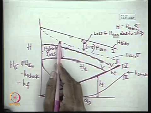
NPTEL’s lecture on centrifugal pump characteristics explains the liquid-pumping duty that remains after priming. It supports curve review; it does not certify a self-priming or vacuum package.
Pertanyaan yang sering diajukan
Does self-priming mean the pump can start completely dry?
No. Confirm the casing preparation and operating limits of the actual design. Do not infer dry-running permission from the self-priming label.
Does vacuum priming eliminate suction lift limits?
No. The main pump still requires acceptable suction conditions at the intended liquid flow. Review elevation, losses, temperature and NPSH separately.
Which arrangement is always faster to prime?
There is no universal answer. Compare the actual suction volume, initial condition, package capacity, controls and a defined acceptance test.
What should a large-flow quotation include?
Request the steady duty curve, priming arrangement, start and restart conditions, operating limits, controls, maintenance requirements and acceptance procedure.