Selecting a variable-frequency drive for a booster pump system starts with the motor and hydraulic duty, then extends to the control method, enclosure, environment, protection, and commissioning. The drive must be compatible with the motor’s voltage, current, frequency, insulation system, speed range, and starting requirements. It must also support the pump’s minimum flow, maximum speed, pressure sensor, staging logic, and fault response. A VFD is not sized from pump horsepower alone and it is not a substitute for a correctly calculated flow and head.
Confirm the pump and motor duty first
Document the pump’s required flow and head at normal, peak, and low-demand conditions. The booster head calculation guide explains why the design point must include elevation, residual pressure, and system losses. The BorraPumps booster-regulator product page asks for inlet and outlet pressure and control requirements; those project values are more useful than guessing a drive size from a picture.
Read the motor nameplate: rated voltage, full-load current, frequency, power, speed, efficiency class, service factor where applicable, connection, and insulation limits. Drive selection should follow the motor current and the manufacturer’s overload category, not only the nominal kW or horsepower. If the motor may run above base speed, confirm that the pump, bearings, seals, and system pressure can tolerate it. If it must run below a certain speed, check cooling and the pump’s minimum stable flow.
Match the drive to the control objective
A pressure-boosting system may use a discharge-header sensor, a remote critical-point sensor, or a combination of pressure and flow signals. The pressure sensor placement guide explains why the measured point must represent the condition the controller is meant to maintain. Specify signal type, range, wiring, failure behavior, and whether the sensor is shared across staged pumps.
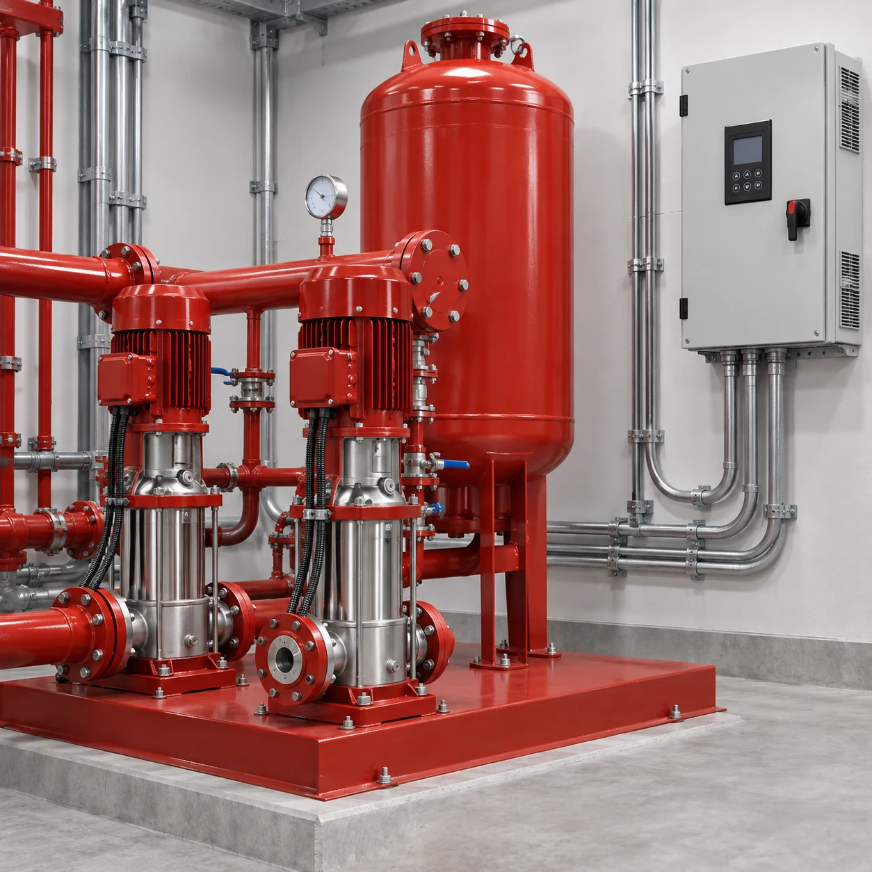
The control loop should ramp speed smoothly, avoid hunting, and hand off to the next pump when the lead pump cannot maintain the setpoint. Define minimum and maximum speed, acceleration and deceleration times, sleep and wake behavior, restart after power loss, and the response to a lost sensor. These settings are commissioning parameters, not universal factory numbers.
| VFD selection input | Почему это важно | Доказательства для запроса |
|---|---|---|
| Motor rated current | Sets thermal and overload capability | Nameplate and motor data sheet |
| Supply voltage and phase | Determines drive compatibility | Site electrical schedule |
| Pump speed range | Protects minimum flow and motor cooling | Pump and motor limits |
| Pressure feedback | Determines control accuracy and failure behavior | Sensor data and control narrative |
| Enclosure and environment | Protects against heat, dust, and moisture | Room conditions and installation location |
| Harmonics and EMC | Affects upstream equipment and wiring | Electrical design requirements |
| Bypass or standby mode | Defines operation when the drive faults | Risk assessment and sequence |
Where a value depends on the project, leave it as an engineering input. Do not invent a universal overload percentage, carrier frequency, or cable length.
Check pump affinity and the system curve
Reducing speed changes pump flow, head, and power according to approximate affinity relationships, but the installed operating point is still where the pump curve meets the system curve. A pressure setpoint that is suitable at one flow can be unstable at another. Check the lowest expected speed, the normal duty, the peak demand, and the transition when another pump starts.
Avoid running a centrifugal pump near shutoff or below the manufacturer’s minimum continuous stable flow. If the building has very small night demand, a pressure vessel, sleep mode, bypass, or smaller trim may be needed. A VFD that simply turns down an oversized pump can still create cycling, heating, or poor pressure response. The two-pump versus three-pump guide explains why staging and drive control should be considered together.
Review electrical installation conditions
Confirm the available voltage, short-circuit current, phase balance, ambient temperature, altitude, ventilation, and panel location. Drives dissipate heat and need clearance around cooling paths. Follow the drive maker’s cable, grounding, shielding, and motor-lead guidance. Long motor cables may require filters or special termination; do not assume a standard cable arrangement is acceptable.
Consider harmonic impact and electromagnetic compatibility where the building has sensitive equipment. A healthcare, laboratory, or data-room project may require more detailed power-quality review than a small plant room. Provide disconnects and lockout provisions that preserve safe maintenance without bypassing required protection.
Select protection and fault behavior
The drive and controller should address dry running or inadequate inlet pressure, overpressure, overcurrent, phase loss, motor overtemperature, sensor failure, and communication loss as applicable. Decide whether a fault stops the whole set, transfers to a standby pump, or holds a safe fallback speed. A “run at maximum speed” response to a failed sensor can create an overpressure hazard and should never be assumed.
Use independent high-pressure and low-inlet protections where the risk assessment requires them. A software limit is not automatically a replacement for a separate protective device. Record alarm thresholds, reset rules, and who is allowed to acknowledge a fault.
Commission at multiple operating points
Commission with a calibrated pressure reference and a known or reasonably measured flow. Record speed, suction pressure, discharge pressure, current, motor status, active pump, and the control signal at low, normal, and peak demand. Test pump staging, lead rotation, a sensor-disconnect case, a drive fault, and a power restoration. Observe whether the pressure overshoots after a valve closes or after another pump starts.

Tune one variable at a time. If the system hunts, check sensor location, trapped air, pump oversizing, vessel pre-charge, valve position, and controller gains before simply slowing the ramp. Keep a final parameter record with drive model, motor data, firmware, setpoints, limits, and date.
Prepare a complete quotation request
Include the duty flow and head, motor nameplate, voltage and frequency, pressure-sensor data, number of pumps, lead/lag sequence, minimum and maximum speed, room conditions, cable lengths, enclosure requirements, harmonic expectations, bypass philosophy, alarms, and commissioning tests. Ask the supplier to identify assumptions and provide a parameter list. The final drive must be verified against the selected motor and pump, not only a nominal catalogue rating.
Treat the motor, cable, and drive as one system
The drive, motor, cable, grounding, and pump form one electrical and hydraulic system. Confirm that the motor is suitable for the drive waveform and that the cable installation follows the drive maker’s requirements. Review bypass operation carefully: a bypass that starts a fixed-speed motor may remove the pressure-control behavior the building relies on. Label the normal path, bypass path, interlocks, and isolation points in the panel documentation.
Avoid copying settings between buildings
A parameter file from another site may contain a different motor current, sensor range, pressure target, ramp time, or staging sequence. Treat it as a reference only. Restore the selected motor data and project limits, then commission with field measurements. Keep a locked copy of the final file and a plain-language record so future service staff know why each limit exists.
Check drive cooling and installation details
The room temperature, altitude, dust, moisture, and panel heat affect the usable drive rating. A drive placed in a warm enclosure may need derating or a cooling arrangement. Keep the manufacturer’s clearance around vents and heat sinks. Separate power and signal wiring as required, bond the equipment correctly, and provide a service disconnect that can be locked out. Confirm that the panel’s protective devices and upstream fault rating match the site design.
When the system has several pumps, write down whether one drive moves between motors or each motor has its own drive. Check what happens when a drive is unavailable. A sequence that looks efficient in normal operation may leave the building without pressure when one common drive fails. Review the emergency and manual modes with the owner before commissioning.
Confirm the handover package
Leave the final drive parameter list, motor nameplate, alarm matrix, wiring record, and measured duty points with the owner. This information makes later troubleshooting safer and prevents a replacement drive from being configured from an unrelated installation.
Engineering sources
Этот US Department of Energy pump-systems resources и pumping-system sourcebook explain system curves, controls, and efficiency considerations. Use them as background and verify final drive and motor settings with the equipment manufacturer and project electrical design.
Часто задаваемые вопросы
Can I size a booster-pump VFD by horsepower alone?
No. Motor rated current, voltage, overload duty, speed range, environment, and the pump control sequence are also required.
Does a VFD guarantee constant pressure?
No. Pressure stability depends on sensor location, hydraulic losses, pump curve, vessel, control tuning, and correct staging.
Can every pump in a set use one VFD?
Some systems use one drive with bypasses or sequential operation, while others use individual drives. The choice depends on the control sequence, failure mode, motor compatibility, and risk assessment.
What should be recorded after commissioning?
Record the final drive and motor data, speed limits, ramp times, pressure setpoint, sensor calibration, alarm behavior, staging thresholds, and measured operating points.
Further learning
The NPTEL IIT Kharagpur lecture on pump characteristic curves is useful background for understanding why the installed system can behave differently from a catalogue point. It is educational material, not a substitute for the selected pump manual, project calculations, or local code review.