
Review an electric fire pump diagram by walking the fire-flow water path from source to discharge header, then isolating the electric driver and controller interfaces, sensing line, and pressure-maintenance branch as separate review lanes. Contractors and buyers use the sketch to assign trade handover points and missing notes. It is not a wiring instruction, lockout procedure, or acceptance certificate.

Part 1. Why Separate Hydraulic Symbols From Power Symbols First?
An electric fire pump diagram usually places piping, valves, and driver or controller notes on one sheet family. Mixing those lanes in conversation causes the electrical trade to chase hose notes and the mechanical trade to argue about feeder language.
| Review lane | Typical symbols / notes | Trade that owns the handover |
|---|---|---|
| Fire-flow water path | Source, suction, pump, discharge header, test outlet | Mechanical / fire protection design |
| Pressure-maintenance branch | Jockey or make-up pump, sensing takeoff | Mechanical with controller coordination |
| Power path | Supply description to controller and motor | Electrical design |
| Alarm / supervisory path | Remote points, naming, annunciation notes | Controls / fire alarm coordination |
Keep the first pass hydraulic. Confirm water source description, isolation points, and whether the sketch shows a usable test path.
Only after that pass should the team enlarge controller and power notes. For cluster context, see the BORRAPUMP Fire Pump guide and the sibling fire pump system diagram article.
Part 2. How Do You Mark the Electric Driver and Controller Boundary?
Locate the motor, the controller enclosure notes, and the documented supply description. Field conductor sizing, disconnect placement, and lockout steps belong to the approved electrical design and the installed manufacturer instructions, not to a blog interpretation of a generic sketch.
| Boundary item | What the drawing should show | Common field confusion |
|---|---|---|
| Motor identity | Frame notes tied to schedule | Assuming any motor of similar horsepower fits |
| Controller identity | Model / feature notes from submittal | Copying lamp meanings from another job |
| Supply description | Voltage, phases, and special constraints as designed | Treating booster panel habits as interchangeable |
| Sensing interface | Connection point referenced to approved layout | Field tee without drawing update |
| Remote signals | Named points, not color folklore | Inventing meanings from LED colors |
When the sketch is silent, escalate to the approved drawing set rather than inventing a temporary field convention. Building booster wiring language is a different duty boundary; see booster pump wiring diagram only as a contrast, not as a substitute.
Part 3. How Should Sensing and Pressure-Maintenance Branches Be Traced?
Pressure maintenance exists to hold system pressure during small leaks or temperature change. It is not the fire-flow pump. Trace the sensing reference separately from the main fire-flow discharge path so start and stop logic is not argued against the wrong flange.
| Branch question | Почему это важно | Escalate when |
|---|---|---|
| Where does sensing take pressure? | Defines control response | Undocumented field takeoff |
| Is the jockey path isolated for service? | Allows maintenance without disabling fire-flow review | No isolation shown |
| Are setpoints on this sheet normative? | Blog sketches must not invent values | Numbers without project basis |
| Does the sketch mix diesel fuel notes? | Electric packages omit fuel interfaces | Wrong driver family assumed |
Important: Do not energize, wire, or adjust an electric fire pump controller from a generic diagram. Follow the approved drawings, site lockout procedures, and the manuals shipped with the installed equipment. (NFPA resources)
Part 4. Which Alarm and Remote Interface Notes Need Owner Names?
Remote points only help if every name maps to a responsible document. List the points shown, then ask which project schedule or controller submittal owns each name. Do not translate lamp colors from a different brand or a prior job.
| Interface note | Document basis | Reject when |
|---|---|---|
| Controller feature list | Submittal / equipment schedule | Feature claimed without model identity |
| Remote alarm names | Approved project documents | Names invented in the field |
| Sensing connection | P and ID or layout drawing | Undocumented tee or hose |
| Test outlet usability | Project test procedure | Outlet missing or unreachable |
Electric sketches often bury sensing and remote annunciation in small notes. Enlarge those notes during coordination meetings so fire alarm, mechanical, and electrical leads share one vocabulary.
Part 5. What Test, Drain, and Gauge Provisions Must Appear?
Before anyone discusses a run, confirm the sketch supports the project’s testing procedure with identifiable outlets, drains, and gauge points. A pretty isometric that cannot support the written test method is incomplete for coordination.
| Provision | Review question | Typical gap |
|---|---|---|
| Test outlet path | Can flow be directed per procedure? | Outlet shown but not accessible |
| Drain / relief notes | Can water be managed during test? | No drain destination |
| Gauge locations | Can operators read what the procedure requires? | Gauges only at convenience points |
| Isolation for service | Can a branch be isolated without guessing? | Missing valves on sensing branch |
Pair this coordination with the sibling electric fire pump testing checklist after the diagram review closes open interface questions.
Part 6. Which BORRAPUMP Routes Follow a Documented Electric Fire Duty?
BORRAPUMP can discuss package options after duty and interface notes are documented. Diagram review itself does not select a model.
| Project signal | BORRAPUMP route | Send with quote |
|---|---|---|
| Integrated electric fire package discussion after duty is documented | EDJ Integrated Fire Pump Set | Fire-flow duty basis, electric supply data, controller feature list, requested documents, destination |
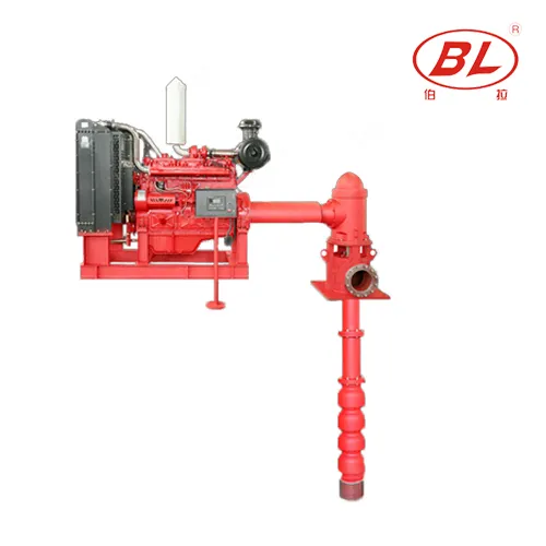
| Vertical turbine diesel fire package when the driver family is diesel, not electric | Вертикальный турбинный дизельный пожарный насос XBC-LC | Confirm driver family first; do not use as an electric substitute |
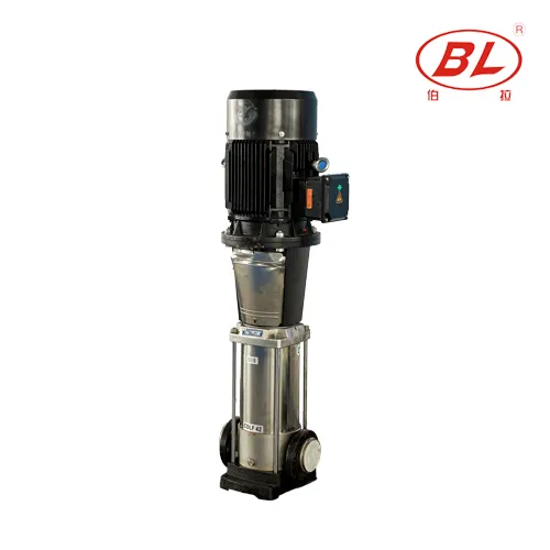
| Pressure-maintenance discussion when jockey duty is separate | CDLF multistage jockey route via fire package inquiry | Sensing concept, maintenance flow expectation, documents |
Why not recommend a building booster wiring article or a landscape booster package here: fire-pump controller and power interfaces are project-specific and are not interchangeable with ordinary building boost documentation.
For documented package questions after interface mapping, use the Fire Pump pillar or contact BORRAPUMP.
Part 7. When Does Diagram Review Stop Being Enough?
Fits:
- Coordination checklists that separate hydraulic, power, sensing, and alarm lanes on an electric fire pump drawing set.
- RFQ preparation after duty and interface notes are written down.
Does not fit:
- Authorizing electrical work, lockout, or controller settings from this article.
- Claiming listing, approval, or acceptance based on reading a blog sketch.
- Substituting booster wiring guidance for fire-pump controller documentation.
Must be confirmed before quote:
- Fire-flow duty basis, electric supply description, controller requirements, sensing concept, remote point list, requested documents, quantity, and destination.
Часто задаваемые вопросы
How is an electric fire pump diagram different from a diesel layout sketch?
Electric layouts emphasize power supply and controller interfaces. Diesel layouts add fuel-system and engine-start interfaces that do not belong on an electric package review.
Can a building booster wiring diagram substitute for fire pump controller notes?
No. Fire-pump controller and power requirements are project-specific and are not interchangeable with ordinary building booster wiring guidance.
Where should the jockey or pressure-maintenance branch appear on the sketch?
On a separate pressure-maintenance path with its own sensing reference, isolation concept, and control notes, not treated as the main fire-flow pump.
Who owns the remote alarm point names shown on the drawing set?
The approved project documents and the installed controller documentation own the names. Field teams should not invent meanings from lamp colors on another project.
Does reviewing this diagram authorize field electrical work?
No. Only authorized personnel working to site procedures and approved drawings may perform electrical work.
Which items should be confirmed before any electric fire pump test run?
Confirm the documented test path, isolation, gauges, drains, and the project testing procedure before any energizing discussion.
Which RFQ fields matter after an electric fire pump diagram review?
Include fire-flow duty basis, electric supply data, controller requirements, sensing notes, connection scope, requested documents, quantity, and destination.
Does completing a diagram review certify the fire pump system?
No. Acceptance requires responsible professionals, applicable authorities, and verified project evidence, not a blog checklist.