
A fire pump and jockey pump diagram should separate the main fire-flow duty from pressure-maintenance duty, then show the water path, controls interfaces, and project records that must be confirmed for the actual system. The diagram is a review tool; it does not certify, approve, size, or set a fire-protection system.

Part 1. Start by Separating the Two Duties
A clear diagram prevents one pump from being described as doing every job. The main fire-pump route is reviewed for the system’s fire-flow function, while the jockey-pump route is reviewed for pressure maintenance. The BORRAPUMP Fire Pump guide provides related cluster context, but the actual project record must state the system objective and the documents that govern it.
| Diagram area | Function to distinguish | Review question |
|---|---|---|
| Main pump route | Fire-flow duty | Is this route clearly separated from pressure maintenance? |
| Jockey-pump route | Pressure-maintenance duty | Is it identified as a different function? |
| Water source and discharge | System water path | Are the endpoints and route documented? |
| Controls interface | Responsibility and signal relationship | Are the project control records identified? |
Part 2. Read the Main Fire-Flow Path
Follow the diagram from water source through the main pump path to the system discharge. Mark the source condition, suction route, pump location, discharge route, and the document references that define the system. A general diagram should expose unknowns rather than invent a pump rating, pressure, flow, or configuration.
| Mark on the diagram | Почему это важно | Must be confirmed |
|---|---|---|
| Water source | Establishes the start of the system path | Actual source conditions |
| Suction and discharge route | Makes the physical route reviewable | Project routing and components |
| Main pump location | Identifies the fire-flow function | Exact product and arrangement |
| System demand interface | Shows where the system receives water | Project demand documentation |
Этот Fire Pump System Diagram covers broader system components. It also should not be used as proof that an unreviewed project meets any standard.
Part 3. Read the Pressure-Maintenance Path
The jockey-pump path should be drawn as a pressure-maintenance function, not as a replacement for the main fire-flow route. Identify where the path connects to the system, how it is represented in the project record, and which actual control documentation applies. Do not add pressure settings or automatic-sequence claims to a generic layout.
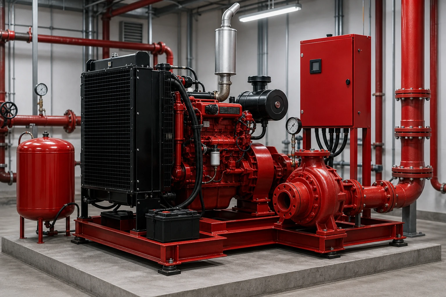
| Pressure-maintenance review item | What the diagram can show | What it cannot establish |
|---|---|---|
| Jockey-pump identity | A distinct role in the layout | Actual model performance |
| Connection point | Relationship to the system path | Pressure settings or sequence |
| Control interface | Need for control documentation | Wiring or alarm values |
| Service access | Location for inspection planning | A test result or approval |
Использовать Что нужно разделить на схеме? for related piping-detail context. Keep all actual settings in the responsible project documents and product instructions.
Part 4. Mark Controls and Project Records for Review
The diagram should name the points where a project needs document review: controller interface, responsible roles, available drawings, product data, inspection records, and handover expectations. It is not a wiring sheet and should not be treated as an instruction to energize, test, or change controls.
| Review record | Why it belongs with the diagram | Boundary |
|---|---|---|
| Current system drawing | Aligns the layout with the project scope | Generic blog art is not a drawing set |
| Product documentation | Connects labels to actual equipment | Family names do not prove suitability |
| Control documentation | Establishes responsibility and interfaces | No wiring or setting inference |
| Inspection or handover plan | Identifies required project evidence | Not a result or acceptance claim |
Important: Do not use a public diagram as evidence of NFPA, UL, FM, code approval, certification, or compliance. Public NFPA resources explain standards context, while the actual project must use its responsible documents and approvals.
Part 5. Turn the Diagram Into a Controlled Inquiry
Attach the marked diagram to a controlled inquiry only after the project has stated the water source, duty objective, system route, installation location, document needs, and destination. That creates a factual discussion path without asking a supplier to infer the system from a keyword.
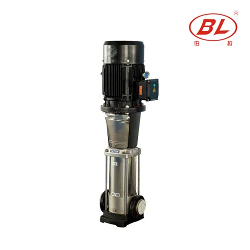
| Documented discussion | BORRAPUMP route | Send with quote |
|---|---|---|
| Integrated package review | EDJ Integrated Fire Pump Set | System objective, source, layout, duty basis, power/driver context, documents, destination |
| Main-pump inquiry | XBC Diesel Engine Fire Pump | Source, route, duty basis, installation location, documents, destination |
| Pressure-maintenance discussion | CDL(F) Вертикальный многоступенчатый подкачивающий насос | System context, pressure-maintenance objective, layout, controls documents, destination |
Share the controlled record with БОРРАПАМП for a project-specific discussion. No product route above is a compliance, configuration, or approval statement.
Part 6. Define What This Fire-System Diagram Cannot Establish
Fits:
- Showing that fire-flow and pressure-maintenance duties are separate in a project review.
- Identifying the water path, controls interfaces, and documents that need confirmation.
Does not fit:
- Establishing NFPA, UL, FM, certification, approval, or compliance status.
- Providing flow, pressure, control settings, wiring, testing, or acceptance instructions.
- Selecting a product without actual system and project documentation.
Часто задаваемые вопросы
What does a fire pump and jockey pump diagram show?
It shows the high-level relationship between the main fire-flow route, the pressure-maintenance route, the water path, control interfaces, and project records. The actual drawing set and product documents provide project-specific detail.
Is a jockey pump the main fire-flow pump?
No. In a system review, the jockey pump is identified with a pressure-maintenance role, while the main pump route is identified with the fire-flow function. Confirm the actual arrangement through project documentation.
Does the diagram prove a code-compliant system?
No. A generic diagram cannot prove certification, approval, or compliance. Those matters depend on the responsible project documents, product evidence, and applicable authority review.
What should be marked on the flow route?
Mark the water source, suction and discharge route, main pump location, system demand interface, installation location, and document references. Record unknowns rather than filling them with assumptions.
What records should be sent for review?
Send the current layout, stated system objective, source and route information, duty basis, installation context, product-document needs, control interfaces, quantity, and destination.
Can this article set pressure or control values?
No. It provides no settings, wiring, or control sequence. Use actual product instructions and the responsible project documentation.
References
- NFPA public resources for standards context; not product or project approval evidence.