
Deep well pump check valve placement should start with the pump manufacturer’s instructions and a verified drawing of the complete well system. Confirm any built-in discharge valve, the pumping water level, drop-pipe construction, operating pressures and local requirements before specifying additional valves. A valve at the surface does not automatically provide the same protection as a correctly selected downhole valve. Equally, copying a spacing rule from another installation can introduce problems. This guide explains how to prepare a defensible placement schedule, distinguish ordinary pressure loss from valve trouble, and ask a supplier for the information needed to review a proposed arrangement.
Start with the actual submersible system
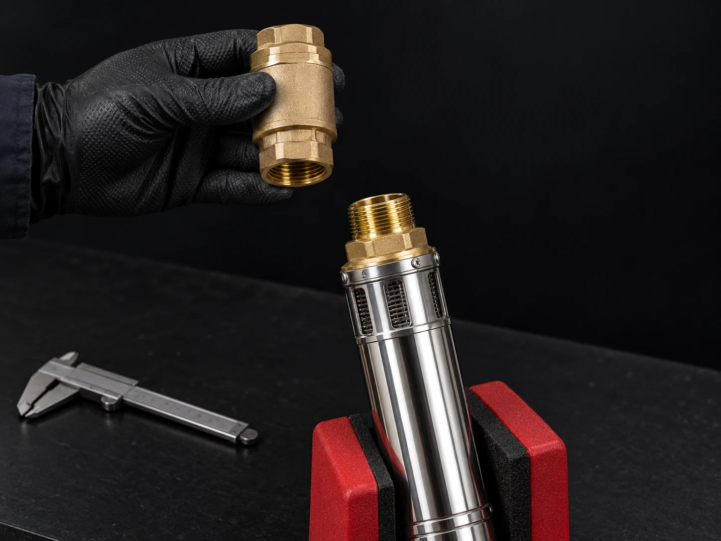
A deep well submersible pump pushes water upward through a discharge riser. When the motor stops, the water column and pressure conditions change. A check valve permits intended forward flow and limits reverse flow through its closing mechanism. Its effectiveness depends on the valve design, its condition and the operating system. It is not simply a fitting that can be added wherever a convenient threaded joint is available.
Identify the pump, motor, riser, fittings, pressure controls, tank or reservoir and delivery network on one drawing. Mark the pump setting depth separately from the static and pumping water levels. These represent different quantities. The water level during sustained pumping can change with flow, season and well condition; the installed pump depth alone cannot describe the hydraulic loading.
เดอะ BorraPumps QJ deep well pump product page is a starting point for an irrigation inquiry. Confirm the specific supplied model and its documented valve arrangement. A catalog photograph cannot establish whether a valve is integrated, its pressure rating, or whether additional valves are required. Request the assembly drawing and installation instructions for the actual order.
Confirm the first valve before adding more
Ask whether the pump discharge contains a check valve and whether that valve is intended to carry the anticipated water column. If the proposed assembly has no integrated valve, obtain written instructions for the external valve position and connection. If it has one, determine whether the manufacturer requires another nearby valve. Do not remove an integrated valve or add a substitute solely because a different installation uses another arrangement.
Review permitted orientation, connecting thread or flange, internal clear passage and closing characteristics. A fitting with the correct nominal connection can still have an unsuitable outside diameter or operating range. Downhole accessories must pass through the usable casing with the cable and other equipment; see the complementary borehole pump diameter selection guide for that physical-space check.
Water Well Journal’s engineering discussion of well-system valves covers valve functions and selection considerations. Use such background to understand the questions being asked, while the final location schedule must come from the responsible designer and the applicable equipment documentation. A general article is not an approved drawing for a particular well.

Why spacing is a project decision
Additional downhole valves are specified in some systems to manage the water column and protect equipment. Their number and spacing should be reviewed against the pump instructions, riser strength, pressure envelope and transient behavior. More valves also introduce more connections and potential service points. Neither one valve for every well nor a fixed universal distance is an adequate design rule.
Compare the proposed layout with the highest and lowest expected pumping water levels. Include the pressure at the receiving network, elevation changes and friction losses while operating. Review what happens when the pump stops, when a valve leaks, and when the next start occurs. These cases can load different sections of pipe and different valves in different ways.
Use the deep well pump head calculation guide to prepare the normal duty calculation. Then ask the designer which shutdown and startup cases require additional analysis. A steady operating head calculation cannot, by itself, establish the pressure peaks associated with rapid flow changes. Normal pressure readings therefore do not prove that a proposed valve schedule is safe.
Record each valve’s depth reference explicitly. A distance measured below ground level is not the same as a distance measured above the pump or relative to the pumping water level. If the drawing and supplier instructions use different references, reconcile them before installation. This small documentation step prevents an otherwise correct recommendation from being installed in the wrong place.
Placement review checklist
| Item to review | หลักฐานที่ต้องขอ | Question the evidence resolves |
|---|---|---|
| Pump discharge arrangement | Model-specific assembly drawing and instructions | Is a valve integrated, and what external arrangement is allowed? |
| Additional downhole positions | Approved depth schedule with a stated reference level | Which sections are protected under the intended operating cases? |
| Valve suitability | Pressure, temperature, water compatibility and orientation information | Can the selected valve operate within this installation’s envelope? |
| Usable casing space | Complete accessory envelope including cable and connections | Can the assembly be installed and retrieved without interference? |
| Surface controls | Tank, pressure sensing and isolation layout | Will controls measure and respond to the intended pressure conditions? |
| การทดเดินระบบ | Recorded flow, pressure and start/stop acceptance procedure | How will correct operation be demonstrated before handover? |
This is a documentation checklist rather than a universal installation specification. Numerical limits must be taken from the selected components, project calculations and local requirements. Do not substitute a pressure rating stamped on a single component for a review of the complete system.
Separate reverse-flow protection from other functions
A check valve is different from an isolation valve, pressure-relief device or a backflow-prevention assembly required by a water authority. The fact that it restricts reverse flow does not mean it meets every contamination-protection requirement. Where irrigation chemicals or another contamination risk are involved, obtain the required arrangement from the responsible authority and designer.
Surface valve placement also needs to preserve the intended relationship between the pump, pressure tank and sensing point. Adding a valve can separate pressure zones. Before changing the arrangement, ask what pressure each control will see during pumping, shutdown and demand. A convenient location near the tank is not sufficient justification for a change.
For agricultural systems, also distinguish a valve within the well riser from equipment serving the irrigation distribution network. The latter can include filtration, pressure regulation and approved backflow protection with separate design purposes. Keep these functions visible on the drawing rather than describing every one-way device as an interchangeable check valve.
Investigate symptoms without guessing
A system that loses pressure after stopping may have a leaking check valve, but it may also have a pipe leak, open demand, a faulty fitting or a measurement problem. Record the pressure change and the conditions under which it occurs. Identify whether demand has genuinely been isolated and whether the gauge and sensing location are suitable. Diagnosis requires a controlled observation, not simply a new valve.
Repeated starting, a pronounced shutdown noise or an unusual restart should trigger a review of controls and hydraulic behavior. Avoid repeated trial starts if abnormal operation could damage equipment. Do not instruct an unqualified operator to open live electrical controls, pull a pump, or dismantle a pressurized connection. Appropriate personnel should isolate electrical and hydraulic energy using the site’s procedures before intrusive work.
Penn State Extension’s water well maintenance and rehabilitation guidance supports keeping well-performance records and investigating deteriorating performance. Compare a suspect system with its earlier flow and water-level records. A well-yield problem or changing sediment conditions will not necessarily be corrected by altering the valve schedule.
Understand water hammer before treating noise
Rapid changes in water velocity can create pressure transients. Valve closing behavior, pipeline properties and operating conditions influence the response. Noise is a useful symptom, but its absence does not demonstrate that every transient is harmless. Conversely, a noise report alone cannot identify which component should be changed.
The following Practical Engineering explanation introduces the physics of water hammer. It is background education rather than instructions for spacing deep well check valves. Ask the project designer to evaluate the actual installation if shutdown pressure changes, reverse flow or unusual restart loading are suspected.
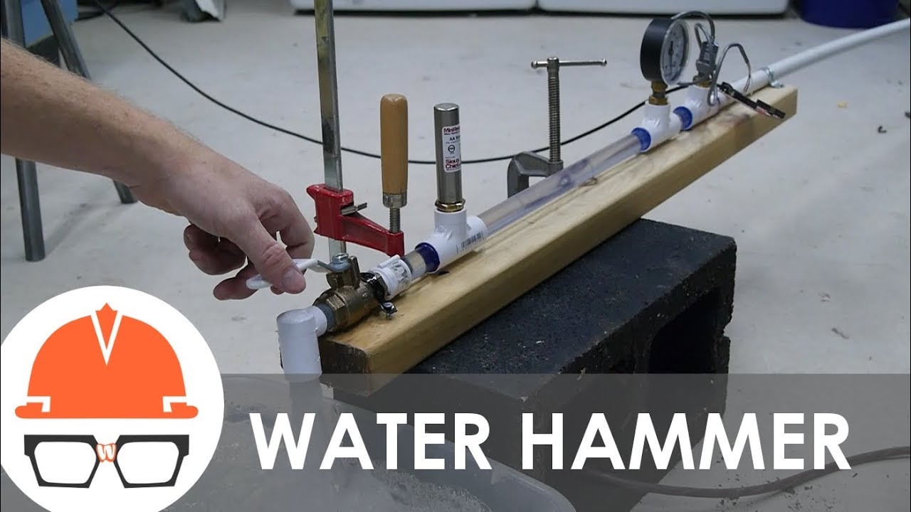
Watch the Practical Engineering explanation.
Specify a reviewable installation and handover
Send the supplier the required flow, receiving pressure, pipe information, installation depth, pumping water-level range and water characteristics. Include the desired operating sequence and whether delivery is to an open reservoir or a pressure-controlled network. Request confirmation of the pump curve and any restrictions affecting starting or stopping. These inputs are more useful than asking how many valves a well of a particular total depth needs.
Before lowering the assembly, reconcile the delivered parts with the approved schedule. Record valve identification, flow direction, connection details and actual installed positions. Keep photographs where practical. The final record should let a future maintenance team understand what was installed without relying on a recollection of the work.
During commissioning, verify the specified flow and pressure, observe starts and stops, and document the applicable acceptance checks. Confirm that protective controls operate as designed and that maintenance personnel receive the final drawing. If results differ from the design, investigate before accepting the installation. For the wider agricultural duty specification, use the deep well irrigation sizing guide alongside this valve review.
คำถามที่มักถูกถาม
Does every deep well pump have a built-in check valve?
No assumption should be made from the product category. Confirm the supplied model’s assembly drawing and installation instructions with the supplier.
Can I use one spacing distance for every well?
No. Review the equipment instructions, pumping water level, riser construction, pressure envelope and startup and shutdown conditions before specifying positions.
Will a surface check valve fix pressure loss?
Not necessarily. Pressure loss can have several causes, and a surface valve can change the relationship between pressure zones and controls. Diagnose the system first.
Is a check valve an irrigation backflow-prevention assembly?
It should not be treated as a substitute. Confirm contamination-protection requirements and the approved device arrangement with the relevant authority and designer.
What should be recorded after installation?
Keep the final valve depth schedule, component identification, connection details, operating measurements and commissioning acceptance records with the well documentation.