การคำนวณเฮดของปั๊มสูบน้ำออกเป็นการกำหนดพลังงานที่ปั๊มต้องเพิ่มให้กับน้ำ เพื่อเคลื่อนย้ายน้ำจากระดับแหล่งน้ำที่เกี่ยวข้องซึ่งอยู่ต่ำที่สุดไปยังจุดระบายน้ำตามอัตราการไหลที่ต้องการ สำหรับบ่อพักน้ำแบบเปิดและทางระบายน้ำแบบเปิด ให้เริ่มจากผลต่างระดับความสูงในแนวดิ่ง จากนั้นบวกการสูญเสียจากแรงเสียดทานในท่อดูดและท่อส่ง รวมถึงการสูญเสียผ่านวาล์ว ข้องอ ตะแกรง และอุปกรณ์บำบัดน้ำ หากระบบรับน้ำปลายทางมีแรงดัน ให้บวกเฮดความดันที่ทางออกด้วย คำนวณที่ระดับน้ำและอัตราการไหลมากกว่าหนึ่งค่า เนื่องจากระดับน้ำในบ่อพักที่เปลี่ยนแปลงและตัวกรองที่อุดตันจะทำให้จุดทำงานเปลี่ยนไป เลือกปั๊มที่เส้นโค้งสมรรถนะของปั๊มตัดกับเส้นโค้งของระบบที่ติดตั้งจริง อย่าเลือกรุ่นโดยพิจารณาจากอัตราการไหลสูงสุดหรือเฮดขณะปิดทางจ่ายเพียงอย่างเดียว ตรวจสอบการเติมน้ำเพื่อไล่อากาศในระบบดูดและค่าเฮดดูดสุทธิที่ต้องการ (NPSH) แยกต่างหาก เพื่อไม่ให้เฮดด้านจ่ายที่คำนวณได้เพียงพอในเชิงตัวเลขบดบังปัญหาการดูดน้ำที่ทางเข้า.
กำหนดระดับอ้างอิงเดียวกันสำหรับค่าระดับความสูงทั้งหมด
เลือกใช้ระดับอ้างอิงจากการสำรวจที่สอดคล้องกัน และบันทึกระดับผิวน้ำต่ำสุดที่สามารถสูบน้ำได้ ระดับน้ำขณะทำงานปกติ ระดับอ้างอิงของปั๊ม จุดสูงสุดตามแนวท่อส่ง และระดับความสูงของทางระบายน้ำปลายทาง สำหรับแหล่งน้ำแบบเปิดและทางระบายน้ำแบบเปิด เฮดสถิตคือผลต่างระหว่างระดับพลังงานของน้ำที่ทางออกกับระดับผิวน้ำของแหล่งน้ำ หากน้ำไหลออกเป็นลำอิสระ ให้ใช้ระดับความสูงของทางออกและเฮดความเร็วที่มีนัยสำคัญตามที่วิธีการออกแบบกำหนด หากน้ำไหลเข้าสู่ท่อที่มีแรงดันหรือถังที่มีระดับน้ำสูงกว่า ให้รวมเงื่อนไขขอบเขตดังกล่าวด้วย อย่านำค่าความลึกที่วัดจากใต้พื้นร่องขุดมาปะปนกับค่าระดับความสูงสัมบูรณ์ของพื้นที่ก่อสร้างโดยไม่แปลงให้ใช้ระดับอ้างอิงเดียวกันก่อน.
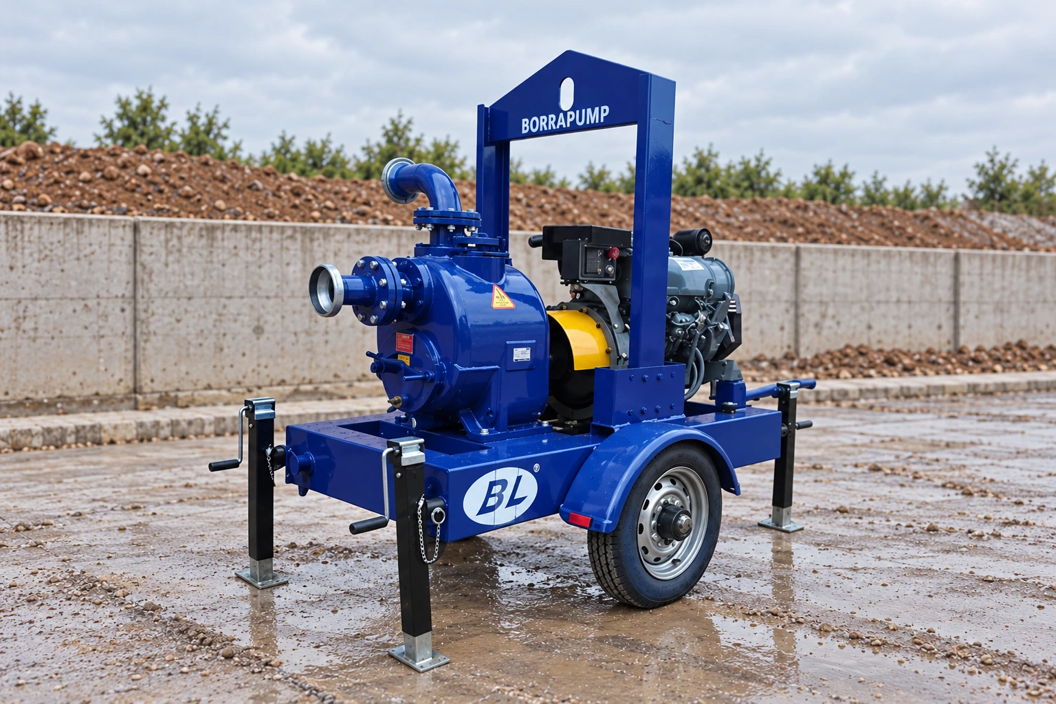
เดอะ ปั๊มสูบน้ำเสียและน้ำที่มีเศษวัสดุแบบติดตั้งบนรถพ่วง BorraPumps SCPY ซึ่งมีความสามารถในการดูดน้ำจากระดับสูง เป็นผลิตภัณฑ์อ้างอิงที่มีอยู่จริง โดยมองเห็นตัวเรือนปั๊มสีน้ำเงิน เครื่องยนต์ ล้อ ขาค้ำยัน และโครงรถได้อย่างชัดเจน ภาพผลิตภัณฑ์ไม่ได้ยืนยันเส้นโค้งเฮด ระยะดูดสูงสุด พิกัดการรองรับของแข็ง หรือกำลังเครื่องยนต์สำหรับโครงการนี้ โปรดขอข้อมูลจำเพาะของรุ่นที่แน่นอน กลุ่มผลิตภัณฑ์ ปั๊มติดตั้งบนรถพ่วง มีตัวเลือกที่เกี่ยวข้องสำหรับงานก่อสร้าง ทั้งนี้ต้องพิจารณาเส้นโค้งสมรรถนะของแต่ละรุ่นแยกกัน.
แยกเฮดสถิตออกจากเฮดที่ขึ้นอยู่กับอัตราการไหล
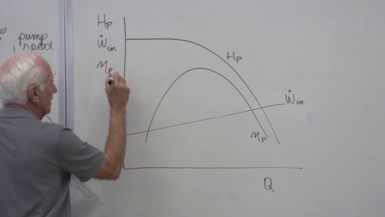
สำหรับเส้นทางการไหลอย่างง่ายจากระบบเปิดไปยังระบบเปิด ให้เขียนสมการดังนี้ Hsystem(Q) = Hstatic + Hpipe(Q) + Hfittings(Q) + Hother(Q). เฮดจากระดับความสูงสถิตยังคงมีอยู่แม้เมื่ออัตราการไหลเป็นศูนย์ การสูญเสียในท่อและข้อต่อจะเพิ่มขึ้นตามอัตราการไหล ซึ่งโดยทั่วไปจะไม่เป็นเชิงเส้น หากทางออกมีแรงดันสูงกว่าความดันบรรยากาศ ให้บวก Δp/(ρg) เพื่อคำนวณผลต่างความดันที่ทางออกตามต้องการ โดยใช้หน่วยที่สอดคล้องกัน หากความเร็วของน้ำที่แหล่งน้ำหรือทางออกแตกต่างกันอย่างมีนัยสำคัญ ให้ใช้พจน์เฮดความเร็วที่เหมาะสมจากสมการพลังงาน สถาบัน Hydraulic Institute มี บทแนะนำเกี่ยวกับเส้นโค้งของระบบ ซึ่งแยกเฮดสถิต การสูญเสียหลัก และการสูญเสียรองออกจากกัน และยังมี เส้นโค้งสมรรถนะของปั๊มและเส้นโค้งของระบบที่นำมาพิจารณาร่วมกัน แสดงให้เห็นว่าเหตุใดจุดตัดจึงเป็นตัวกำหนดอัตราการไหลจริง.
ใช้ข้อมูลเส้นผ่านศูนย์กลางภายในท่อ วัสดุและความขรุขระของผิวท่อ ความยาวสายยาง ข้องอ วาล์วกันกลับและวาล์วปิด-เปิด ตะแกรงกรอง รวมถึงอุปกรณ์กรอง ตกตะกอน หรือบำบัดน้ำทุกชนิด สายยางแบบแบนสำหรับงานชั่วคราวที่มีความยาวมากอาจเปลี่ยนแปลงทั้งความยาวและเส้นทางการเดินสายตามความคืบหน้าของงาน หน่วยบำบัดที่อุดตันอาจทำให้เกิดการสูญเสียแรงดันมากกว่าช่วงที่เริ่มเดินระบบ การอ่านค่าแรงดันใกล้ปั๊มไม่ได้แสดงภาพรวมทั้งหมด เว้นแต่จะทราบขอบเขตของทางออกและการสูญเสียทั้งหมดที่เกิดขึ้นระหว่างทาง.
คำนวณตัวอย่างที่ตรวจสอบได้อย่างชัดเจน
สมมติว่าบ่อสูบน้ำในพื้นที่ขุดที่กำหนดขึ้นเพื่อเป็นตัวอย่าง มีระดับน้ำต่ำสุดตามการออกแบบอยู่ที่ระดับความสูง −6 ม. และมีทางระบายน้ำออกแบบอิสระที่ระดับ +2 ม. โดยใช้ระดับอ้างอิงเดียวกัน ดังนั้นผลต่างระดับสถิตเท่ากับ 8 ม.. ที่อัตราการไหลออกแบบซึ่งกำหนดแยกต่างหาก สมมติว่าการสูญเสียแรงเสียดทานในท่อด้านดูดและด้านจ่ายที่คำนวณได้รวมกันเท่ากับ 4 ม., และวาล์ว ข้องอ และอุปกรณ์บำบัดทำให้เกิดการสูญเสียเพิ่มเติม 2 ม.. ดังนั้น เฮดรวมที่ระบบต้องการในเบื้องต้นคือ 8 + 4 + 2 = 14 ม. ที่อัตราการไหลดังกล่าว. นี่เป็นเพียงการคำนวณเพื่อประกอบตัวอย่าง ไม่ใช่ค่าพิกัดสมรรถนะของ SCPY หากทางออกมีแรงดัน เฮดแรงดันที่ทางออกจะต้องนำมาบวกเพิ่มด้วย หากเส้นทางการเดินท่อหรืออัตราการไหลเปลี่ยนแปลง จะต้องคำนวณการสูญเสียใหม่.
อย่านำระยะยกด้านดูด 6 ม. มาบวกซ้ำอีกครั้งหลังจากคำนวณผลต่างระดับความสูงจากแหล่งน้ำถึงทางออกได้ 8 ม. แล้ว เพราะจะทำให้เกิดการนับระยะยกสถิตบางส่วนซ้ำซ้อน อย่างไรก็ตาม ด้านดูดยังคงต้องตรวจสอบการล่อน้ำของปั๊มและค่า NPSH แยกต่างหาก กระทรวงพลังงานของประเทศไทย คู่มือการใช้งานระบบสูบน้ำ อธิบายเฮดรวม เส้นโค้งของระบบ และความไวของอัตราการไหลต่อแรงดันย้อนกลับ.
| อินพุต | ค่าตัวอย่าง | เหตุผลที่นำมารวม | หลักฐานของโครงการ |
|---|---|---|---|
| ระดับความสูงต่ำสุดของแหล่งน้ำ | −6 ม. | กำหนดระยะยกสถิตที่เลวร้ายที่สุด | การสำรวจและการควบคุมระดับ |
| ระดับความสูงของจุดปล่อยน้ำแบบเปิด | +2 ม. | กำหนดขอบเขตทางออก | การสำรวจแนวเส้นทาง |
| ผลต่างระดับสถิต | 8 ม. | ยังคงมีอยู่แม้ในสภาวะอัตราการไหลต่ำ | การลบค่าระดับโดยใช้จุดอ้างอิงเดียวกัน |
| แรงเสียดทานในท่อและสายยาง | 4 ม. | Rises with flow and length | Diameter, length, roughness, flow |
| Fittings and treatment | 2 ม. | Adds component losses | Valve/filter supplier curves |
| Illustrative total | 14 m | Duty at the assumed flow | Verify against exact pump curve |
All numbers in the table are hypothetical. Replace them with the actual survey, flow and component data before procurement.
Use the flow requirement from the water balance
The pump must deliver a flow that controls groundwater, rain runoff, construction water and any planned drawdown within the allowed time. The excavation dewatering flow calculation guide develops that time-based inflow estimate. Head is then calculated at that flow. Choosing a pump by head first and accepting whatever flow the curve gives may leave the sump rising during a storm. Conversely, a high flow at very low head on a brochure does not prove the pump will deliver the required site flow.
When two pumps run in parallel, they share approximately the same head but combined flow follows their curves and the common system curve. A standby pump selected for reliability should be tested against the duty it must carry alone. A long discharge header, backflow device or sediment filter can change both operating points. Do not multiply one-pump catalogue flow by two without a combined-curve check.
Check suction lift and priming separately
A surface-mounted trailer pump placed above the source needs enough pressure and priming capability at the inlet. The vertical source-to-pump lift, suction hose loss, temperature, altitude and available atmospheric pressure affect priming and NPSH. These terms are not an excuse to add suction lift twice to the total head. Calculate NPSH available using the selected pump’s suction datum and compare with its NPSH-required curve at each duty. Request priming data for the actual hose length and water level.
If the source level falls, static total head rises and inlet margin worsens. Both can reduce delivered flow. The self-priming suction-pipe sizing article explains hose diameter and air-leak checks for self-priming installations; the trailer model may have a different priming system that must be confirmed from its manual. Move the pump or redesign the intake if the verified lift exceeds its limit.
Account for temporary-site changes
Construction dewatering routes move as excavations deepen and work areas shift. A discharge hose may be extended around traffic, elevated over a berm, or connected to a treatment tank. Each change alters the system curve. Define the worst credible route and the stages at which recalculation is required. A hose that kinks or collapses can cause far more loss than assumed; inspect actual lay-flat hose when pressurized. Check the outlet for erosion and backpressure from high water in the receiving area.
NPTEL IIT Guwahati’s dewatering methods overview distinguishes sump, wellpoint and bored-well layouts. The selected method must suit the excavation and groundwater-control objective; the final arrangement must also meet local discharge and sediment-control requirements. A filter may need cleaning or replacement; include its dirty-condition loss when checking whether the pump can maintain the duty.
Read the actual pump curve
Mark the calculated head at the required flow on the exact SCPY model’s curve, including speed and impeller configuration. Confirm motor or engine power, efficiency, minimum and maximum operating flow, and solids capability. The actual operating point is the curve intersection; if no intersection meets the duty, change the pump or system design. A unit with a higher shutoff head may still perform poorly at the design flow. Do not accept a quotation that shows only one headline maximum.
For a power check, hydraulic power is ρgQH, where density is kg/m³, Q is m³/s and H is m. Shaft input is higher because pump efficiency is below one, and engine or motor input is higher still after driver losses. Use actual liquid properties and manufacturer efficiency at the duty point. The diesel versus electric dewatering guide addresses the driver decision after the hydraulic point is known.
Verify with field measurements
At commissioning, measure source water elevation, discharge outlet condition, flow, suction and discharge pressure, hose configuration, motor or engine speed and load, and filter differential pressure. Compare measured duty with the calculated curve. A pump that shows the expected discharge gauge pressure but insufficient flow may be working against more friction or backpressure than estimated. A noisy inlet with low flow may instead be a suction problem. Change one variable at a time and retain the record.
Set level alarms and a failure response before leaving the pump unattended. Repeat measurements after moving the hose or cleaning treatment equipment. The temporary nature of a site is a reason to check the calculation often, not to select from an oversize rule of thumb. The correct head is tied to a route, a flow and a water level, all of which can change.
คำถามที่มักถูกถาม
ฉันควรเพิ่มแรงดันดูดเพื่อเพิ่มระดับการระบายน้ำหรือไม่?
ใช้ความแตกต่างระดับน้ำจากแหล่งน้ำเข้าสู่จุดจ่ายน้ำให้เท่ากัน หากความแตกต่างดังกล่าวรวมถึงตำแหน่งของปั๊มแล้ว ให้ไม่เพิ่มระดับแรงดูดอีก.
ความหนาแน่นของหัวเป็นแบบคงที่เหมือนกับความหนาแน่นของหัวแบบไดนามิกทั้งหมดหรือไม่?
ไม่ จำนวนหัวน้ำรวมถึงการสูญเสียท่อ สายพาน ท่อต่อ และอุปกรณ์ต่างๆ ที่ขึ้นอยู่กับปริมาณการไหล และความดันที่ต้องการในการระบายน้ำ.
Can the pump’s maximum head rating be used as the design duty?
ไม่ หัวฉีดสูงสุดหรือหัวฉีดที่ปิดการทำงานจะทำงานเมื่อมีปริมาณการไหลน้อยหรือไม่มีเลย อ่านปริมาณการไหลที่ต้องการจากรูปโค้งที่ระบุ.
เมื่อใดจึงควรทำซ้ำการคำนวณ?
ตรวจสอบใหม่อีกครั้งเมื่อระดับแหล่งน้ำ การสูงของจุดจ่ายน้ำ ความยาวของท่อกรอง ความต้องการปริมาณน้ำ หรือการรวมกันของปั๊มที่ใช้งานเปลี่ยนแปลงไปอย่างมาก.
การเรียนรู้เพิ่มเติม
Cal Poly Pomona’s บรรยายเกี่ยวกับคุณสมบัติของปั๊มแรงเหวี่ยง explains pump curves and their intersection with a pipe network. Use the selected trailer pump’s own curve for the actual site calculation.