
Pump shaft straightness measurement starts by defining the drawing requirement, support arrangement, reference surfaces and measurement method. A dial indicator reading on a rotating shaft is a surface runout measurement under that setup; it is not automatically a complete measurement of the shaft’s geometric straightness. Journal roundness, dirt, support errors and gravity can influence the result. This guide explains how to plan and document a bench investigation after pump dismantling, distinguish the quantities being checked and decide when specialist metrology is needed. It provides no universal allowable bend, runout limit or permission to straighten a shaft.
Define the question before selecting the indicator
Determine whether the investigation concerns a suspected bent shaft, a journal that does not run true relative to a specified datum, a seal surface, or assembled rotor behaviour. These questions can require different setups and acceptance requirements. Obtain the shaft drawing and identify its datum system, relevant surfaces and geometric controls. A general maintenance instruction to “check shaft runout” needs clarification if the result will decide whether an expensive component can return to service.
The NIST dimensional metrology programme provides background on reliable dimensional measurements. The practical lesson is to match the measuring method and its capability to the defined requirement. Do not select a convenient indicator first and interpret whatever it reads as straightness afterward. Record the measurement objective in the job sheet so that the operator, repair contractor and final reviewer are evaluating the same property against the same equipment document.
Preserve the as-found shaft condition
Before disassembly, retain relevant symptoms and operating evidence: vibration observations, rubbing, seal leakage, abnormal bearing condition and the event that prompted removal. These observations help frame the investigation but do not themselves prove a bent shaft. Identify component orientation and protect datum surfaces during removal. Avoid supporting or clamping the shaft on a surface whose damage is part of the investigation unless the method specifically accounts for it.
Clean the shaft using the approved process. Inspect journals, shoulders, keyways, threads and seal contact areas for raised metal, deposits and damage. A burr at a support location can create a repeatable but misleading indicator pattern. Preserve photographs before correcting removable surface defects, and record any preparation performed before measurement. If cracks, severe corrosion or heat damage are suspected, hold the shaft for appropriate examination. A dimensional check cannot establish the absence of material damage or approve reuse of a shaft that fails a separate inspection requirement.
Select supports and datums deliberately
Possible setups include specified centres, precision supports or a specialist instrument. The suitable arrangement depends on the shaft design and drawing. Centres are useful only if their condition and relationship to the required datum are appropriate. V-blocks introduce their own contact geometry and can interact with journal form errors. Do not treat a rough bench, two loose blocks and a hand-held indicator as a controlled acceptance setup.
Record support locations, contact surfaces and shaft orientation. Consider the effect of shaft weight and span, particularly for long or slender parts. Moving supports changes the elastic deflection and may change the observed readings without changing the shaft’s permanent condition. Where the accepted method requires compensation or specialist analysis, have that method defined before measurement. The EPRI pump maintenance resource supports disciplined component inspection within a wider maintenance process, but its general guidance does not supply the datum definition or allowable deflection for a particular shaft.
Establish a repeatable indicator setup
Mount the indicator on a stable fixture, set the contact direction and preload as required by the instrument procedure, and ensure that the tip can follow the selected surface without crossing a keyway, groove or damaged edge. Mark the axial stations and angular reference. Rotate slowly by the approved manual method, keeping fingers away from pinch points and preventing the shaft from rolling off its supports. This is a bench inspection, not a powered trial run.
At each station, record the maximum and minimum readings over the required rotation and the angular positions. Preserve the signed or referenced readings where the method needs them, rather than recording only a final difference. Repeat the cycle to check consistency. An unstable fixture, dirt on a support or a changing contact angle can produce poor repeatability. Stop and correct the setup before collecting more numbers. More readings from an unstable arrangement do not make the final conclusion more reliable.
| Setup item | Neden önemli | Record required |
|---|---|---|
| Drawing and inspection objective | Defines the property and limit being assessed | Revision, datum and applicable requirement |
| Support locations | Influences alignment and gravity effects | Locations and contact surfaces |
| Instrument and contact orientation | Determines measurement capability and response | Instrument ID, calibration and setup photograph |
| Axial and angular stations | Makes patterns comparable | Station map and reference mark |
| Repeat cycles | Reveals unstable setup or handling effects | Individual readings and observed variation |
The table describes the inspection record. It does not specify an acceptable runout or straightness value.
Interpret runout without overstating straightness
For an indicator sweep, total indicated variation is the difference between the highest and lowest readings at that station under the defined setup. For example, a maximum of plus 0.04 mm and a minimum of minus 0.01 mm give an indicated variation of 0.05 mm. This arithmetic example is not an acceptance limit and does not establish a 0.05 mm shaft bend. The surface geometry and relationship to the supports still require interpretation.
Do not automatically divide every reading by two and call the result straightness error. That shortcut assumes a geometric model that may not apply to the actual surface, supports or drawing control. Compare patterns across stations and check whether the results repeat after an approved repositioning or setup verification. If the decision depends on distinguishing centreline geometry from journal form or datum error, use a qualified measurement method. Explain the result in the report as “indicator variation at station X under setup Y” unless the method genuinely supports a stronger geometric conclusion.
Separate shaft condition from assembled rotor condition
A shaft can meet a defined bench check while the assembled rotor still has problems caused by fits, debris, component seating or other assembly conditions. Conversely, a component surface may show runout without proving that the entire shaft centreline is bent. Preserve the boundaries of the test. Inspect the mating journals, shoulders, sleeves, impeller seats and coupling interfaces using their own requirements.
Compare this work with Mil anahtarlık incelemesi ve shaft thread inspection. These address local features that can affect assembly but are not substitutes for geometric measurement. If a rotor is reassembled after repair, carry out the specified assembly verification separately. Do not use a balance certificate as proof of shaft straightness or a straightness report as proof of balance. Each test addresses a different property, and the release package should identify what was actually checked rather than combine them under a vague “rotor checked” label.
Decide on reuse, repair or replacement
Compare valid measurements with the approved requirement, considering the method’s capability and uncertainty. Record accepted, rejected and held-for-review conditions explicitly. If the shaft is outside the specified condition or the result is ambiguous, obtain an engineering disposition. Avoid attempting local heating, hammer straightening or unsupported pressing as a workshop improvisation; a repair can affect material condition, residual stress and other shaft features.
An approved repair instruction should define the process, subsequent examinations, dimensional verification and documentation. Replacement also requires confirmation of material, dimensions, interfaces and any model-specific features. A shaft that is straight but has an incorrect bearing seat or damaged thread may still be unsuitable. Keep the original as-found measurements alongside the final values. This makes it possible to review what changed and prevents the final report from hiding the original defect behind a single accepted measurement collected after repair.
Prepare a useful supplier handover
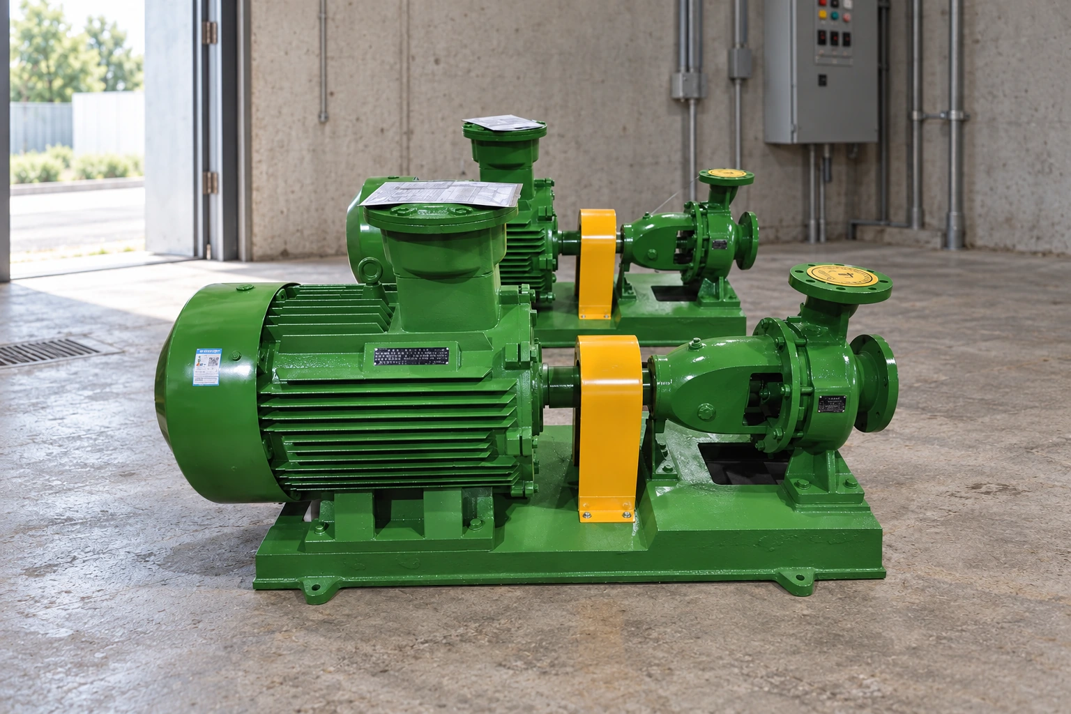
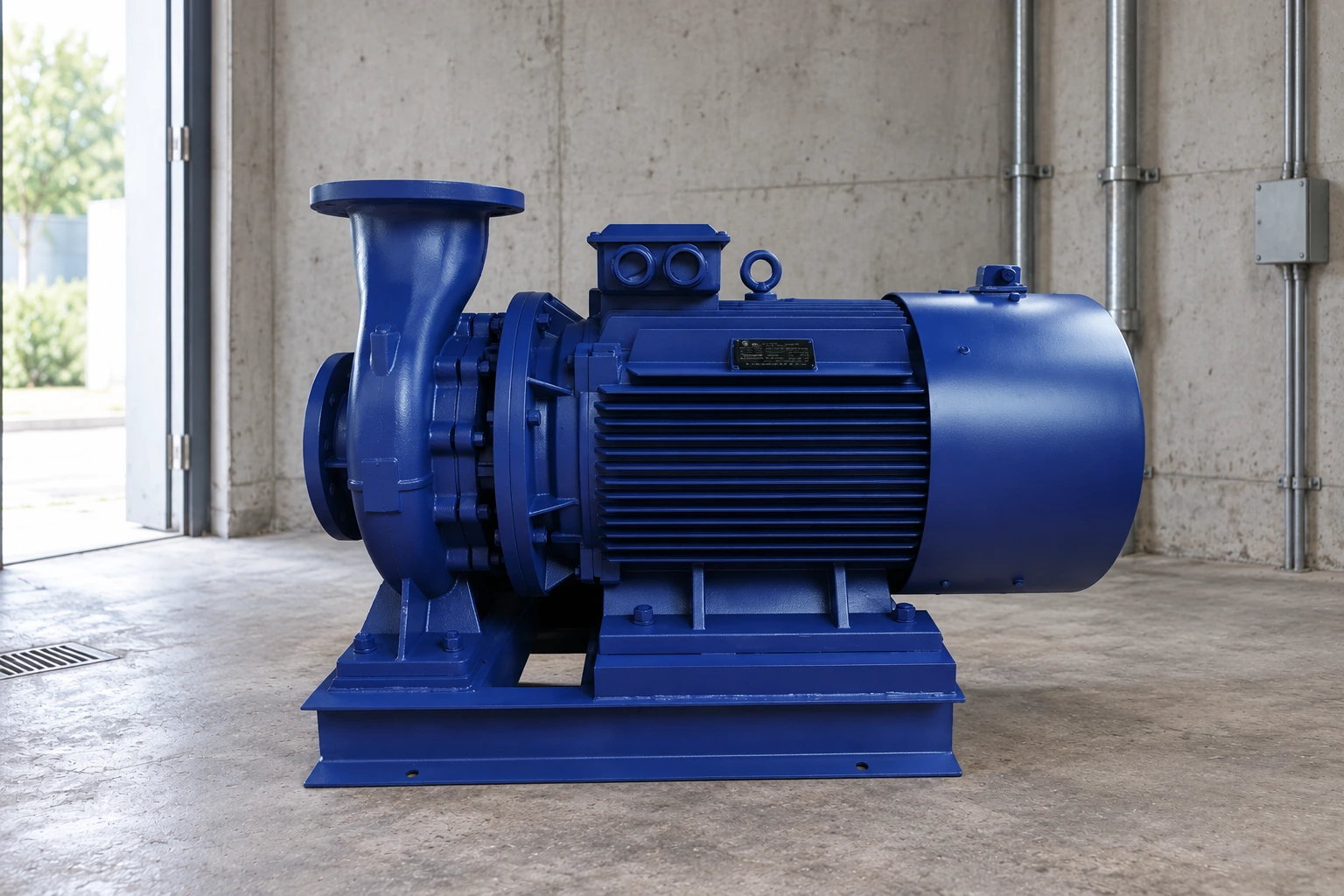
Ayrıca IS temiz su santrifüj pompası, identify the actual supplied shaft through the equipment serial number and drawing. Photographs of the complete pump cannot establish internal shaft dimensions or the allowed geometric condition. Send the inspection objective, shaft identification, support map, instrument details, raw readings, photographs and the applicable limits with the inquiry.
Connect these findings to the maintenance inspection report and retain relevant shaft corrosion evidence. A clear handover lets the reviewer distinguish permanent deformation from an unresolved setup issue, and lets purchasing request a traceable replacement when necessary. It also avoids repeated measurement using different undocumented supports, where apparently conflicting results consume time but cannot be compared. State which questions the present inspection answers and which still require assembled checks or specialist examination.
Further learning: dimensional limits and fits
The IIT Kanpur NPTEL lecture below introduces limits, fits and tolerances. It is useful background for reading dimensional requirements. It does not demonstrate this shaft setup or define a pump shaft straightness limit; follow the equipment-specific metrology procedure.

Sık sorulan sorular
Is dial indicator runout the same as straightness?
No. The indicator records surface variation relative to its setup. A straightness conclusion requires a method that addresses the drawing requirement and separates relevant surface, datum and support effects.
Can two different support spans give different results?
Yes. Support condition and gravity-related deflection can affect the observed readings. Record the specified arrangement and compare results only when the methods and conditions are understood.
What is the acceptable shaft runout?
Use the value and method specified for the exact shaft or assembly. There is no single value in this guide that can safely be applied to every pump size, speed, material and bearing arrangement.
Does a balanced rotor prove the shaft is straight?
No. Balance and geometric condition are separate properties. Keep their inspection and acceptance records distinct and carry out both when the equipment procedure requires them.
What if the readings do not repeat?
Investigate fixture stability, cleanliness, support contact, handling and instrument setup before making an acceptance decision. Do not average unstable readings into an apparent pass.