
Pumps in series add head at the same flow through each pump. Pumps in parallel add their individual flows at a common head across the connected branches. Those rules describe how to construct a combined pump curve; they do not guarantee that a real system will deliver double the head or double the flow at its operating point. The actual result comes from the intersection of the combined pump characteristic and the system curve, together with suction conditions, controls, pressure limits, and each pump’s approved operating range.
Define the duty problem before choosing an arrangement
Start by stating what is inadequate: flow at a required pressure, head at a required flow, operating flexibility, or availability when equipment is unavailable. These are different requirements. Adding a second pump can fail to solve the problem if the real restriction is a blocked pipe, an unsuitable suction source, a control limitation, or an incorrectly calculated duty.
Record the present flow, suction and discharge conditions, liquid temperature, speed, valve positions, and tank levels. Compare those measurements with the installed pump’s documented curve. Use the Görev noktası hesaplama kılavuzu to assemble the system requirement. Distinguish measured values from estimates and retain the assumptions used for friction losses and static head.
A standby pump can be installed in a parallel piping arrangement without normally operating at the same time as the duty pump. Therefore, the pipe arrangement alone does not establish the operating philosophy. Write down whether the objective is duty/standby availability, staged capacity, or continuous combined operation before assessing performance.
Understand the series relationship
In a simple series train, the discharge from one pump supplies the next. With no intermediate branch, the same delivered flow passes through both. At a selected flow, read the head developed by each pump and add those heads to construct the combined characteristic. Repeat at several flows rather than adding only the two rated-head values.
The downstream pump receives an inlet condition influenced by the upstream unit. Its casing, seal chamber, flanges, and connected equipment must be suitable for the resulting pressure conditions. A unit acceptable as an independent pump may not be suitable as the second pump in a series train. Obtain the manufacturer’s confirmation rather than treating the hydraulic addition rule as approval to connect two available machines.
Series operation also requires attention to starting, stopping, failure, and bypass arrangements. Consider what happens if one pump is stopped, a check valve closes, or an upstream pump trips. Do not assume that every stopped pump may safely pass the required flow or be driven by reverse flow. These are installation-specific questions for the equipment supplier and system designer.
Understand the parallel relationship
In parallel operation, branches connect common suction and discharge systems, subject to the actual layout. For a selected differential head, obtain the flow contributed by each pump and add those flows. Construct the combined curve point by point. When branch losses differ, the head available across each actual pump may also differ, so the simplified common-head assumption needs refinement.
For identical pumps under equivalent conditions, the flow contributions may be similar. For different pumps, one can contribute more than the other. At some system conditions, a pump may contribute little or no useful flow. Review the complete curves, branch losses, check valves, and operating limits rather than assuming that a larger and smaller pump will share duty in proportion to motor size.
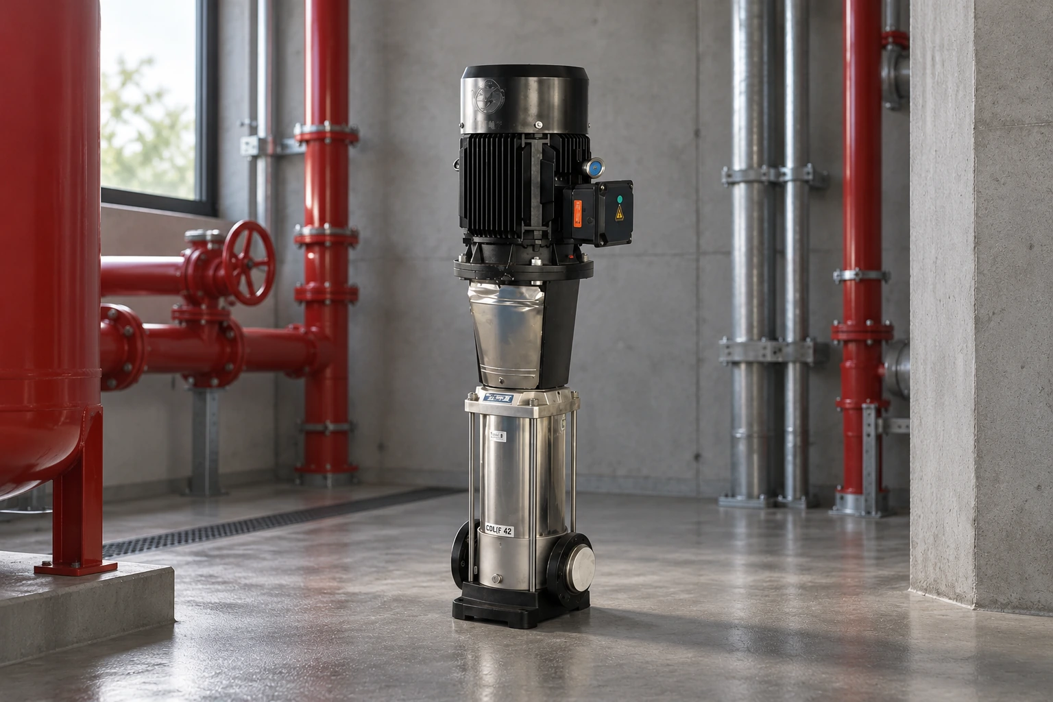
The hidrofor su besleme ekipmanı is a useful product route when requesting an engineered multi-pump supply arrangement. Ask for the proposed operating sequence and combined performance, not just the number of pumps mounted on the frame. The catalog image does not establish the control sequence or delivered duty of a project-specific package.
Find the new system operating point
The system curve represents the head required to move different flows through the installation. A common simplified water-system model combines a static component with flow-dependent friction losses. The actual form depends on the system and controls. A new combined pump curve intersects that requirement at a new operating point; it does not simply multiply the original duty coordinates.
For illustration, two identical parallel pumps may each be capable of a certain flow at a selected head. Adding their flows at that head constructs one point on the combined curve. If the increased system flow requires greater friction head, however, the actual intersection can occur at a higher head and lower combined flow than a simple doubling of the original operating flow would suggest.
Likewise, two series pumps can raise the available head, but the resulting higher flow through the same pipeline increases friction. Evaluate the intersection rather than promising that the installation will produce twice its former pressure at the same unchanged operating condition. The curve-reading guide explains how to keep curve conditions and axes consistent.
Compare the arrangements using project evidence
| Soru | Series arrangement | Parallel arrangement |
|---|---|---|
| How is the ideal curve combined? | Add heads at a common flow | Add flows at a common head |
| What procurement check is especially important? | Downstream inlet and pressure-boundary suitability | Stable sharing and each branch’s operating range |
| What changes the actual duty? | System resistance and total available head | System resistance and total available flow |
| What control cases need review? | Start/stop order and loss of one stage of pumping | Pump staging, check-valve action and one-pump duty |
| What must not be assumed? | Any pump can accept the boosted inlet pressure | Two pumps will double the installed operating flow |
These are comparison principles, not a complete design specification. The US Department of Energy’s Pomp sistemleri kaynakları emphasise the value of system-level assessment. Use the required duty range and the actual system conditions to choose the arrangement rather than starting with a preferred pump count.
Check suction conditions for every operating combination
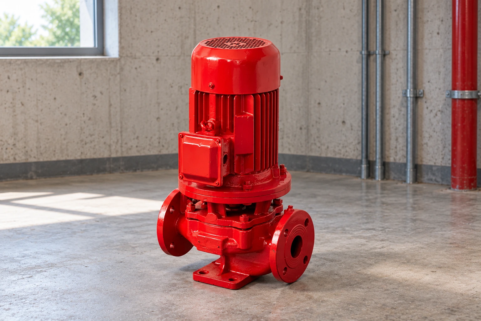
More flow through a common suction line can increase its losses. A source that supplied one pump adequately may not supply two parallel pumps under the new total flow. Review source levels, inlet pressure, liquid temperature, shared pipework, strainers, and branch geometry. Compare the available NPSH with the manufacturer’s requirement and the applicable margin for every intended combination.
The Hydraulic Institute explains the connection between NPSH and operating regions. An apparently attractive combined duty is not acceptable if one machine operates outside its approved range or lacks an adequate suction condition. The Gerekli kılavuzla karşılaştırıldığında mevcut NPSH provides a practical checklist of the information to gather.
For a series train, the upstream pump’s suction condition remains a critical boundary. Pressure added later cannot correct cavitation already occurring in the first pump. For parallel pumps, assess both common and branch losses. Avoid reducing the review to a single source-pressure reading obtained when only one unit was running.
Review one-pump operation and staging
A parallel set should be assessed with one pump operating as well as with the intended combined combinations. When another pump stops, the remaining unit moves to a different point on its own curve. Check the resulting flow, head, power, and minimum-flow condition. A pump selected only for the all-pumps-running case can be unsuitable when it operates alone.
Staging controls need an intentional sequence, suitable measurement locations, and stable transitions. The Görev/bekleme konfigürasyon kılavuzu addresses availability and changeover considerations. For capacity staging, establish how demand is detected, which unit starts next, and how the system avoids excessive cycling or unstable sharing.
Variable speed can improve flexibility, but it does not remove the need for curve and operating-limit checks. Use speed-specific curves and verify the permitted range. A control description that says “automatic alternation” does not, by itself, explain what happens during a high-demand event, a sensor fault, or a single-pump failure.
Request a combined performance package
Send the supplier the liquid, required duty range, source conditions, installation layout, static levels, expected operating combinations, electrical supply, and pressure constraints. Request individual and combined curves, the proposed sequence, power requirements, operating restrictions, and a commissioning test plan. Identify which party is responsible for the system curve and surge assessment.
At commissioning, record each agreed operating combination under known conditions. Confirm the contribution of each pump where the instrumentation permits, and compare the result with the approved package. Investigate unexpected sharing, noise, current, or pressure before accepting the installation. Keep the final control settings and curve revisions with the operating documents so later changes can be assessed consistently.
Gelişmiş öğrenme
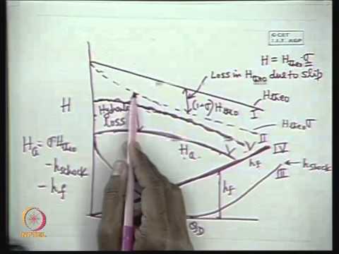
NPTEL’s lecture, “Mod-01 Lec-15 Characteristics of a Centrifugal Pump,” explains the pump-performance background needed to combine and interpret curves. Use it alongside the actual supplier curves; it does not certify a particular series train or parallel package.
Sık sorulan sorular
Do two parallel pumps always double the flow?
No. The combined curve adds flows at a common head, but the actual installed flow is determined by the system curve and operating constraints. Greater flow usually changes friction losses in the connected pipework.
Do two series pumps always double the operating head?
Not as a universal installed result. Heads are added at a specified common flow when constructing the combined curve. The operating flow and head then depend on the complete system and permitted conditions.
Can different pump sizes run in parallel?
Potentially, but only after a curve, sharing, control, and operating-range assessment. A smaller pump can contribute little at the head established by a larger pump, and stable operation cannot be assumed.
Is a standby pump the same as a capacity pump?
No. Standby operation provides availability when another unit is unavailable. Capacity operation intentionally uses multiple pumps to meet demand. A package can support both purposes, but its approved sequence must explain how.
What is the most useful document to request?
Request a combined performance and control package tied to the actual system duty range. It should include the individual curves, intended combinations, suction and pressure constraints, and the acceptance checks for commissioning.