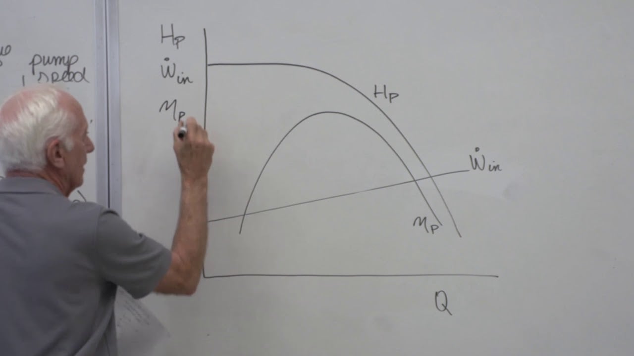
A dewatering pump head calculation determines the energy the pump must add to move water from the lowest relevant source level to the discharge point at the required flow. For an open sump and open outlet, start with the vertical elevation difference, then add suction and discharge pipe friction and losses through valves, bends, screens and treatment equipment. Add outlet pressure head if the receiving system is pressurized. Calculate at more than one water level and flow because a changing sump and fouling filter move the operating point. Select the pump where its curve meets the installed system curve; do not choose a model from maximum flow or shutoff head. Check suction priming and net positive suction head separately so a numerically adequate discharge head does not hide an inlet failure.
Establish the same datum for every elevation
Choose a consistent survey datum and record the lowest pumpable water surface, normal operating level, pump reference elevation, high points in the discharge route, and final outlet elevation. For an open source and open outlet, static head is the difference between outlet water energy elevation and source water surface. If the outlet is a free jet, use the outlet elevation and any material velocity head specified by the design method. If it enters a pressurized pipe or a tank with a higher water level, include that boundary instead. Do not mix a depth measured below a trench floor with an absolute site elevation without converting both to the same datum.
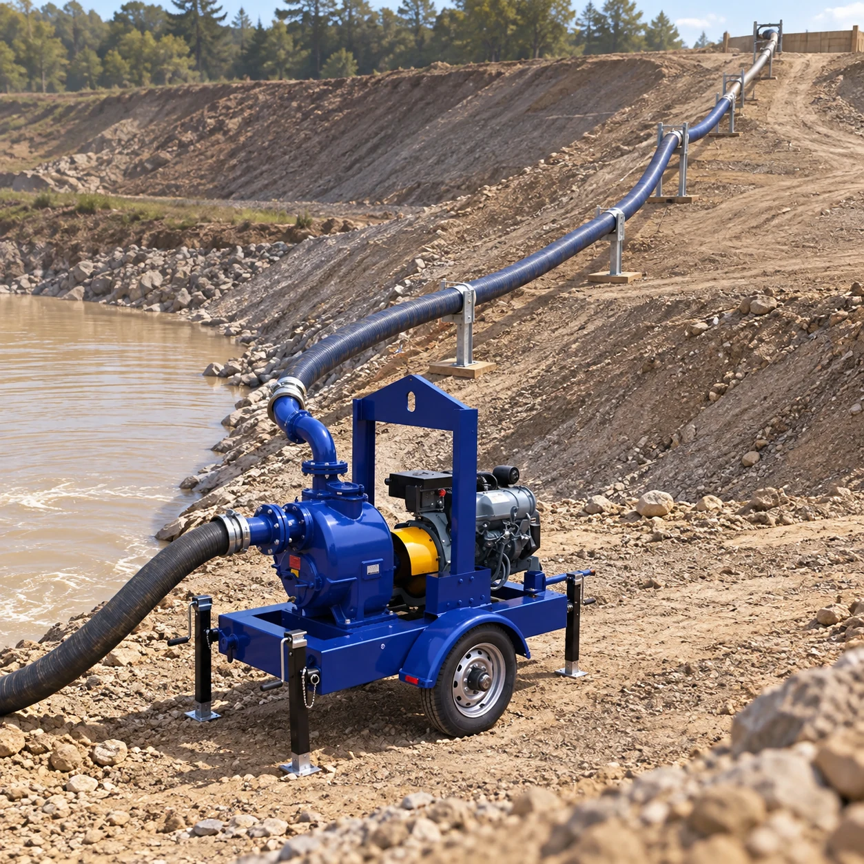
ال BorraPumps SCPY high-suction-lift trash-water trailer pump is a real product reference. Its blue pump casing, engine, wheel, stabilizing jacks and frame are visible. The product image does not establish a head curve, maximum lift, solids rating or engine power for this project. Obtain exact model data. The trailer-pump range gives related site options, subject to their own curves.
Separate static and flow-dependent head
For a simplified open-to-open route, write Hsystem(Q) = Hstatic + Hpipe(Q) + Hfittings(Q) + Hother(Q). Static elevation head remains even at zero flow. Pipe and fitting losses increase with flow, usually nonlinearly. If the outlet has pressure above atmosphere, add Δp/(ρg) for the required outlet pressure difference, with consistent units. If source or outlet velocity differs materially, apply the appropriate velocity-head terms from the energy equation. The Hydraulic Institute’s system-curve tutorial separates static, major and minor losses; its combined pump and system curves show why the intersection determines actual flow.
Use pipe internal diameter, material and roughness; hose length; elbows; check and isolation valves; strainers; and any filter, settlement or treatment equipment. A long temporary lay-flat hose can change length and route as work progresses. A clogged treatment unit can add more loss than it did at commissioning. A pressure reading near the pump does not tell the whole story unless the outlet boundary and all intervening losses are known.
Work a transparent example
Assume a hypothetical excavation sump has its lowest design water level at elevation −6 m and a free discharge outlet at +2 m on the same datum. Static difference is 8 m. At a separately determined design flow, assume calculated suction and discharge pipe friction totals 4 m, and valves, bends and treatment add 2 m. The initial required system head is 8 + 4 + 2 = 14 m at that flow. This is an illustrative calculation, not an SCPY performance rating. If the outlet becomes pressurized, its pressure head must be added; if the route or flow changes, losses must be recalculated.
Do not add the 6 m suction lift again after calculating the 8 m source-to-outlet elevation difference; that would double count part of the static lift. The suction side still requires a separate priming and NPSH check. The US Department of Energy كتاب الموارد المتعلقة بنظام الضخ describes total head, system curves and the sensitivity of flow to backpressure.
| مدخل | Example value | Why it is included | Project evidence |
|---|---|---|---|
| Lowest source water elevation | −6 m | Sets worst static lift | Survey and level controls |
| Open discharge elevation | +2 m | Defines outlet boundary | Route survey |
| Static difference | 8 m | Exists even at low flow | Same datum subtraction |
| Pipe and hose friction | 4 m | Rises with flow and length | Diameter, length, roughness, flow |
| Fittings and treatment | 2 m | Adds component losses | Valve/filter supplier curves |
| Illustrative total | 14 m | Duty at the assumed flow | Verify against exact pump curve |
All numbers in the table are hypothetical. Replace them with the actual survey, flow and component data before procurement.
Use the flow requirement from the water balance
The pump must deliver a flow that controls groundwater, rain runoff, construction water and any planned drawdown within the allowed time. The excavation dewatering flow calculation guide develops that time-based inflow estimate. Head is then calculated at that flow. Choosing a pump by head first and accepting whatever flow the curve gives may leave the sump rising during a storm. Conversely, a high flow at very low head on a brochure does not prove the pump will deliver the required site flow.
When two pumps run in parallel, they share approximately the same head but combined flow follows their curves and the common system curve. A standby pump selected for reliability should be tested against the duty it must carry alone. A long discharge header, backflow device or sediment filter can change both operating points. Do not multiply one-pump catalogue flow by two without a combined-curve check.
Check suction lift and priming separately
A surface-mounted trailer pump placed above the source needs enough pressure and priming capability at the inlet. The vertical source-to-pump lift, suction hose loss, temperature, altitude and available atmospheric pressure affect priming and NPSH. These terms are not an excuse to add suction lift twice to the total head. Calculate NPSH available using the selected pump’s suction datum and compare with its NPSH-required curve at each duty. Request priming data for the actual hose length and water level.
If the source level falls, static total head rises and inlet margin worsens. Both can reduce delivered flow. The self-priming suction-pipe sizing article explains hose diameter and air-leak checks for self-priming installations; the trailer model may have a different priming system that must be confirmed from its manual. Move the pump or redesign the intake if the verified lift exceeds its limit.
Account for temporary-site changes
Construction dewatering routes move as excavations deepen and work areas shift. A discharge hose may be extended around traffic, elevated over a berm, or connected to a treatment tank. Each change alters the system curve. Define the worst credible route and the stages at which recalculation is required. A hose that kinks or collapses can cause far more loss than assumed; inspect actual lay-flat hose when pressurized. Check the outlet for erosion and backpressure from high water in the receiving area.
NPTEL IIT Guwahati’s dewatering methods overview distinguishes sump, wellpoint and bored-well layouts. The selected method must suit the excavation and groundwater-control objective; the final arrangement must also meet local discharge and sediment-control requirements. A filter may need cleaning or replacement; include its dirty-condition loss when checking whether the pump can maintain the duty.
Read the actual pump curve
Mark the calculated head at the required flow on the exact SCPY model’s curve, including speed and impeller configuration. Confirm motor or engine power, efficiency, minimum and maximum operating flow, and solids capability. The actual operating point is the curve intersection; if no intersection meets the duty, change the pump or system design. A unit with a higher shutoff head may still perform poorly at the design flow. Do not accept a quotation that shows only one headline maximum.
For a power check, hydraulic power is ρgQH, where density is kg/m³, Q is m³/s and H is m. Shaft input is higher because pump efficiency is below one, and engine or motor input is higher still after driver losses. Use actual liquid properties and manufacturer efficiency at the duty point. The diesel versus electric dewatering guide addresses the driver decision after the hydraulic point is known.
Verify with field measurements
At commissioning, measure source water elevation, discharge outlet condition, flow, suction and discharge pressure, hose configuration, motor or engine speed and load, and filter differential pressure. Compare measured duty with the calculated curve. A pump that shows the expected discharge gauge pressure but insufficient flow may be working against more friction or backpressure than estimated. A noisy inlet with low flow may instead be a suction problem. Change one variable at a time and retain the record.

Set level alarms and a failure response before leaving the pump unattended. Repeat measurements after moving the hose or cleaning treatment equipment. The temporary nature of a site is a reason to check the calculation often, not to select from an oversize rule of thumb. The correct head is tied to a route, a flow and a water level, all of which can change.
الأسئلة الشائعة
Do I add suction lift to discharge elevation?
Use one consistent source-to-outlet elevation difference. If that already includes the pump’s position, do not add suction lift again. Check suction margin separately.
Is static head the same as total dynamic head?
No. Total head also includes flow-dependent pipe, hose, fitting and treatment losses and any required outlet pressure.
Can the pump’s maximum head rating be used as the design duty?
No. Maximum or shutoff head occurs at little or no flow. Read the head at the required flow from the exact curve.
When must the calculation be repeated?
Recheck it when source level, outlet elevation, hose length, filter, flow requirement or operating pump combination changes materially.
التعلم المستمر
Cal Poly Pomona’s ندوة عن خصائص المضخة الطاردة explains pump curves and their intersection with a pipe network. Use the selected trailer pump’s own curve for the actual site calculation.