
An eccentric reducer at pump suction is commonly installed flat side up in a horizontal liquid line to avoid a high pocket where gas can collect. That familiar rule is only a starting point. Correct orientation also depends on the upstream pipe slope, whether the supply comes from above or below, liquid behavior, priming requirements and the pump manufacturer’s instructions. Review a side elevation of the complete suction route before approving the fitting. A reducer symbol in a plan view cannot show whether the finished line contains an air pocket.
The practical objective is to deliver suitable liquid conditions to the inlet while avoiding trapped gas, excessive losses and unacceptable piping loads. An eccentric reducer is one part of that arrangement. It cannot compensate for an undersized suction line, a leaking connection, inadequate submergence or a poor inlet layout.
Understand what eccentric geometry changes
A concentric reducer keeps the centers of its two ends on one axis. An eccentric reducer offsets them, allowing one side to remain straight when viewed along the appropriate plane. In a horizontal liquid suction line, a level upper surface can avoid the raised crown that a concentric fitting may create. However, the adjacent pipe geometry determines whether gas actually has a route out of the system.
The fitting also changes the flow area and velocity. Even with a sensible orientation, it adds a local hydraulic effect that belongs in the suction-system assessment. Its geometry, length, diameter ratio and relationship to nearby fittings may matter. A nominal diameter label alone does not describe the inlet flow reaching the impeller.
The University of Pretoria hosts a review of pump suction reducer selection examining eccentric and concentric arrangements. It is useful background for questioning a blanket rule. Apply the findings through the actual pump and piping design, rather than assuming one orientation is universally superior.
Draw the suction route in elevation
Show the minimum and maximum liquid levels, pipe centerlines, changes in elevation, reducer orientation, valves, strainers and the pump inlet. Mark the direction of flow. Add the relevant dimensions and identify whether the drawing represents the installed line or a proposed modification. A photograph can supplement this information but may hide slope and elevation differences.
For a tank-fed line, follow the upper internal profile from the source toward the inlet. Identify places where gas could collect and ask how it would leave during filling and normal operation. For a suction-lift arrangement, also review priming and the possibility of air entering connections that operate below atmospheric pressure. Do not assume a leak will always appear as liquid escaping outward.
If the source is overhead, a vertical drop and horizontal turn may require a different analysis from a line rising toward the pump. Likewise, a vertical suction connection does not inherit every detail of the horizontal flat-side-up convention. Record the geometry and obtain design approval when the common arrangement does not clearly fit the installation.
Compare layouts without turning conventions into absolutes
| Layout condition | Main question | Drawing or check required |
|---|---|---|
| Horizontal liquid line approaching the inlet | Could the crown trap gas? | Side elevation showing the reducer and adjacent pipe profile |
| Suction lift with a rising line | Can the line fill and retain prime? | Full suction route, connections and approved priming method |
| Feed from an elevated source | Does the transition create a local high pocket? | Vertical drop, elbow and reducer arrangement together |
| Vertical pump suction connection | What inlet geometry does this pump require? | Pump nozzle orientation and manufacturer’s piping instructions |
| Liquid carrying settling solids | Can the arrangement create accumulation zones? | Solids characteristics and operating velocity review |
These checks do not establish a universal straight-run length or reducer angle. Use the applicable pump and piping requirements. Where a layout departs from the supplier’s recommendation, document the reason and the acceptance basis rather than relying on an unsupported rule from a generic sketch.
Keep gas pockets and cavitation as separate questions
Trapped gas can interfere with liquid delivery and priming. Cavitation involves vapor formation when local pressure becomes sufficiently low for the liquid conditions. Both may cause unstable operation, but their causes and remedies differ. A flat upper reducer surface may address one potential gas trap while leaving an inadequate suction pressure margin unchanged.
Evaluate suction losses with the actual flow range, pipe sizes, fittings and liquid properties. Include the minimum source level and relevant temperature conditions. Strainer loading, temporary commissioning screens and valve positions can change the losses from those assumed in the original calculation. Identify the worst relevant combination rather than checking only the normal clean condition.
ال U.S. Department of Energy pumping sourcebook explains the importance of evaluating a pump with its system. Use that system approach when reviewing a reducer modification. Changing a fitting should not be represented as a guaranteed cure for every suction-side problem.
Review nearby elbows, valves and strainers
An elbow immediately before a reducer may influence the inlet flow differently from a long approach pipe. Several closely spaced fittings can interact. Check the manufacturer’s inlet piping guidance for the actual pump configuration, including any restrictions on valve placement and approach geometry. Do not transfer requirements between horizontal end-suction and other pump designs without review.
A suction valve needs the correct type and operating position for the design. A partly closed valve may create losses that overwhelm any benefit from a carefully oriented reducer. Strainers need an appropriate service and maintenance plan; their clean pressure loss is not the same as their loaded condition. Keep these checks connected to the operating record.
Consult the existing suction strainer pressure-drop article for the separate monitoring question. The reducer review concerns geometry and inlet conditions, while strainer assessment concerns changing resistance. Combining the two investigations avoids replacing a fitting when the dominant restriction is elsewhere.
Make orientation explicit in procurement and installation
A purchase request should include end sizes, dimensional standard, material, pressure and temperature requirements, connection details and the required eccentric orientation on the installation drawing. Those items are engineering inputs; this guide does not assign a universal material or rating. Ensure the fitting supplied matches the approved piping specification.
Mark the flat side on a controlled drawing and reference a physical elevation or direction that installers can identify. Expressions such as “top” become ambiguous when a pipe is sloped or a spool is turned during fabrication. Confirm orientation after final placement, not only when the spool is on the workshop floor.
Check for internal intrusion from gaskets, weld debris or temporary protection. Verify that supports and anchors hold the line in its intended position. Do not pull a misaligned spool into place using the pump flange bolts. A piping layout that looks hydraulically sensible can still impose unacceptable mechanical loads on the casing.
Relate the layout to the correct pump family
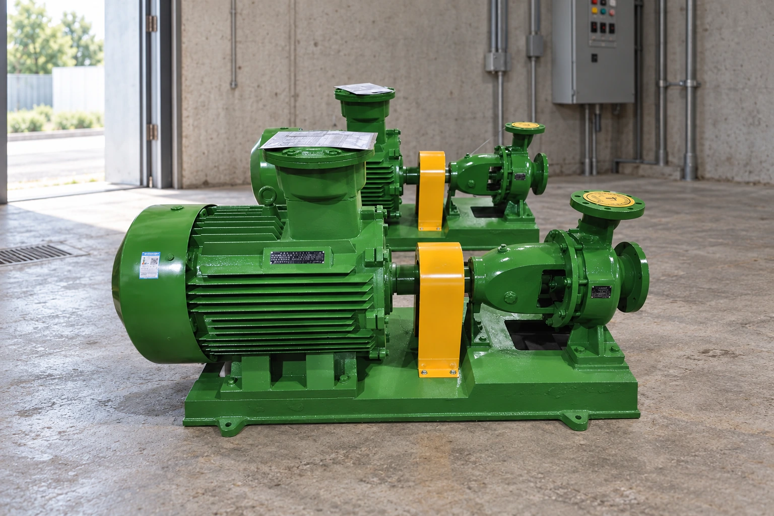
ال مضخة المياه المركزية من نوع IS is a relevant starting point for an end-suction layout discussion. Request the actual outline drawing and inlet requirements for the selected model. An external product image cannot establish reducer dimensions, allowable nozzle loads or the required inlet approach.
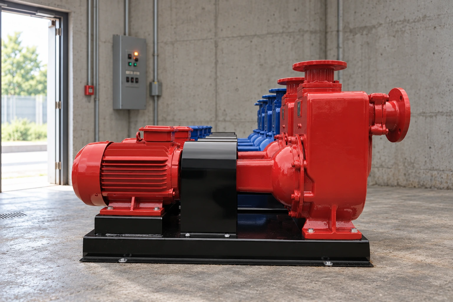
ال ZW self-priming sewage pump illustrates a different service context where the liquid and priming requirements must be considered together. A self-priming designation does not remove suction-line design responsibilities. The product photographs here show pump families, not an approved connected piping arrangement.
For mechanical acceptance, use the separate pump nozzle-load verification guide. It addresses forces, moments and documentation at the connection. Reducer orientation should be settled alongside that review, while keeping hydraulic and mechanical acceptance criteria clearly identified.
Verify the completed arrangement before operation
Compare the installed line with the approved elevation drawing and record deviations. Confirm the valve lineup, filling method, vent provisions and instrumentation under the site’s commissioning procedure. If gas must be removed, use approved facilities and safe handling procedures. Never loosen an operating pressure joint to improvise a vent.
At commissioning, record the actual liquid level, temperature, flow, inlet pressure, discharge pressure and speed. Note whether the system was fully filled and whether temporary strainers were installed. These details make subsequent troubleshooting meaningful. A successful short run at a high source level does not validate operation at the lowest design level.
If instability remains, investigate the whole suction system rather than rotating the reducer repeatedly without evidence. Check connection tightness, submergence, source conditions and resistance before approving another modification. The accompanying Practical Engineering video explains the relationship between pump flow and system pressure; it provides background rather than a fitting installation instruction.
الأسئلة الشائعة
Should the flat side always face upward?
Flat side up is common in horizontal liquid suction lines to avoid an upper gas pocket. The full pipe elevation, supply direction and pump instructions still control the design. Vertical or unusual approach arrangements require their own review.
Can a concentric reducer ever be used at pump suction?
It may be acceptable in an appropriate geometry with the necessary engineering review. Do not reject or approve it solely by name. Assess gas accumulation, inlet flow conditions, losses and the manufacturer’s requirements for the selected pump.
Will an eccentric reducer prevent cavitation?
It cannot guarantee that. Orientation may help avoid a gas pocket, while cavitation assessment requires the actual suction pressure conditions, vapor pressure and pump requirements. Other suction-line restrictions or low source levels may remain critical.
How much straight pipe is required before the pump?
Use the selected pump’s inlet piping requirements and the actual arrangement. There is no single length in this article that applies to every pump, fitting combination and duty. Record the supplier’s requirement on the approved drawing.
What information should be sent for a layout review?
Provide the pump model, nozzle drawing, suction-route elevation, fitting details, liquid and solids information, flow range, source levels and temperature range. Include pressure-loss calculations and known commissioning problems so orientation is assessed in context.