A booster pump pressure sensor should measure the pressure the control system is actually meant to protect or maintain. For a simple building domestic-water set, that may be a stable discharge-header point downstream of the pumps and check valves. For a long or zoned distribution system, a remote critical-point sensor may better represent the pressure available to users, but it adds communication, reliability, and commissioning requirements. Keep suction-pressure protection separate from discharge control. Select a sensor location, range, and setpoint from the hydraulic design, then verify them while the system operates at low and peak flow. There is no universal distance from the pump that suits every building.
Decide what pressure the controller needs to know
The measured variable must match the control objective. A discharge-header sensor can maintain the pressure at the plant. It does not directly report pressure at the highest or most distant fixture. Pressure losses between the header and that fixture rise with flow; a constant plant setpoint may be adequate at light demand but insufficient during a peak if it was chosen without the network losses. Conversely, setting a high plant pressure to cover the worst-case path at all times can overpressure low floors and waste energy.
A remote sensor at a critical branch can support pressure control closer to what the users need. It must be located at a representative point, not a convenient but rarely critical outlet. If several zones or branches compete, one remote point may cease to govern after a valve or tenancy changes. An engineer may select multiple measurements or a reset strategy, but the control sequence must explain which signal governs and what happens if a signal is lost.
The BorraPumps booster-regulator water supply equipment is a clean-water boosting package type whose control mode should be confirmed for the selected model. Its product page asks the buyer for flow, head, inlet and outlet pressure, and control requirements. Do not assume the pictured package includes a particular sensor type, wiring, or remote-control feature.
Separate discharge control, suction protection, and monitoring
A building may need several pressure measurements with different jobs. The control sensor provides feedback to a variable-speed drive or staging controller. A suction-pressure sensor or switch can stop or inhibit pumps when the inlet source is inadequate. A monitoring gauge helps operators compare field pressure with a transducer signal. A single sensor should not be assumed to perform all three functions safely without a documented control and protection design.
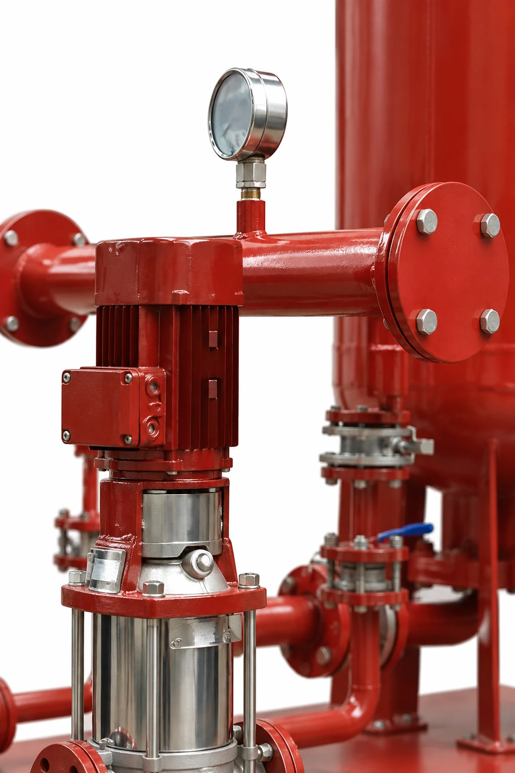
Place a discharge control tap where water is well mixed and the reading is not dominated by turbulence from an elbow, check valve, throttling valve, or pump outlet. Follow the selected transmitter’s installation instructions for orientation, isolation, impulse connection, environmental rating, and any straight-run requirement; do not apply an arbitrary universal number of pipe diameters. A service valve may help replacement, but it also creates the possibility of a sensor being isolated while the controller still thinks the reading is valid. Address that failure in the control narrative.
The ASHRAE handbook’s variable-speed pumping discussion describes the importance of sensing at a point that represents the controlled hydraulic condition in hydronic systems. Domestic-water boosting is not the same as a closed hydronic loop; use this as a control principle, not a domestic plumbing code. The US Department of Energy pumping-system sourcebook similarly stresses that pump and system curves and control method must be considered together.
| Sensor or reading | Main purpose | Location question | Failure to avoid |
|---|---|---|---|
| Discharge-header pressure | Control local plant pressure | Is it downstream of check valves and representative of delivered pressure? | Reading pump pulsation or an isolated branch |
| Remote critical-point pressure | Control user-end pressure | Does this point still govern at peak and low flow? | Treating one tenant branch as every zone |
| Suction pressure | Protect source and diagnose inlet loss | Is the tap at the actual pump inlet boundary? | Mistaking upstream utility pressure for pump suction |
| Local test gauge | Independent field check | Can it be read at the same hydraulic point? | Comparing gauges across an unaccounted valve or elevation |
The table identifies design checks rather than mandatory locations for every project. The selected arrangement must follow applicable plumbing, electrical, and instrumentation rules. For a hospital, coordinate any control change with the facility’s water and continuity program; the hospital booster selection guide explains why a stable pressure display is not the whole resilience test.
Relate the setpoint to the hydraulic calculation
Start with the pressure required at the controlling fixture or equipment. Add the vertical elevation difference and downstream losses at design flow to determine the header pressure that would satisfy that point, then account for the minimum available inlet pressure when selecting the pump’s required differential head. The building booster head calculation guide shows the boundaries and unit conversions. Do not set a discharge sensor to an arbitrary “high enough” value or copy a pressure from a different building.
If the sensor is at a remote location, its target may correspond more directly to the residual pressure needed there. However, the controller must also prevent unacceptable high pressure near the pump or lower floors at low demand. Pressure-zone design and a high-pressure limit remain necessary. A remote sensor cannot fix an inadequate pump curve, an empty break tank, or a restricted suction line.
For example, if a hypothetical upper-floor outlet needs 20 psi while design-flow losses from the plant to that outlet are 18 ft of water, those losses represent about 7.8 psi for ordinary-temperature water. If that outlet is 75 ft above the plant, the elevation term is about 32.5 psi. A preliminary plant setpoint at peak would therefore need to cover approximately 20 + 7.8 + 32.5 = 60.3 psi at the plant reference, before any other project-specific terms. This arithmetic does not establish a code requirement or safe pressure for lower floors. The actual loss, elevations, fixture requirement, and zoning must be verified. A discharge setpoint selected from this one peak case may be unnecessarily high at low flow; the controller strategy must address both cases.
Select the sensor range and signal behavior
Choose a pressure range that covers normal operation and credible high-pressure events while providing useful resolution over the control band. A transmitter with a very broad range can make small control changes harder to measure accurately; one with a range too narrow can saturate or be damaged. Check compatibility with potable-water requirements where applicable, pressure rating, process connection, electrical output, enclosure rating, supply voltage, and calibration procedures. Do not infer any of these details from a pump image.
The controller should detect an open circuit, short, out-of-range value, frozen value where supported, or communication loss. Define whether it stops pumps, holds a safe speed, switches to a local backup sensor, or requires an operator. These responses depend on the building’s risk assessment. A sensor failure should not silently command maximum speed and expose lower-floor plumbing to overpressure.
Distinguish a pressure reading from pump-running proof. A running motor does not prove water flow; a static vessel can briefly hold pressure after a pump trip. Use the appropriate combination of pressure, flow, motor status, and alarms for the failure modes the owner has specified. The Department of Energy pump-systems resources discuss control strategy as part of overall pumping performance, not as an isolated sensor purchase.
Commission at several operating points
At installation, verify transmitter zero and span according to the manufacturer, compare its reading with a calibrated independent gauge at the same elevation and hydraulic point, and record the controller’s displayed value. Then test low flow, normal occupancy, design or representative peak, lead-pump changeover, and a loss of sensor signal. If a remote sensor is used, record both local header and remote pressure simultaneously. This reveals whether the assumed distribution losses and control response match reality.
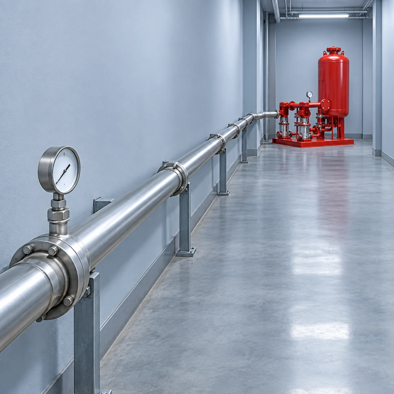
Observe stability as fixtures open and close. A hunting pressure trace can be caused by controller tuning, sensor location, trapped air in a sensing line, an oversized pump, a poorly selected pressure vessel, or fast staging. Do not “fix” hunting by raising the setpoint without diagnosis. Check the duty/standby configuration guide for how pump transitions should be tested under a defined failure case.
Record the final sensor tag, physical location, calibration, setpoint, alarm limits, lead/lag thresholds, firmware or controller settings, and as-built wiring. This record is essential when a future tenant change or pump replacement alters the hydraulic conditions. The BorraPumps water-supply booster product range can be reviewed for candidate equipment, but the final sensor placement and settings belong to the project-specific control design.
Common placement and setup mistakes
Avoid mounting the sensor at a convenient but isolated pipe pocket, comparing a remote reading to a plant gauge without elevation correction, using the same device for control and low-suction protection without failure analysis, choosing a range with poor useful resolution, and leaving the isolation valve closed after service. Another mistake is assuming a discharge-header reading guarantees upper-floor service at peak. It only measures that header; distribution losses still have to be calculated or measured.
Frequently asked questions
Should the pressure sensor be at the pump discharge or the farthest fixture?
It depends on the control objective and network. A local header sensor is simpler and can work when downstream losses and zoning are handled in the setpoint. A remote sensor can reflect user-end pressure but needs robust communication and failure handling.
Is the suction-pressure switch the same as the control sensor?
No. Suction protection checks source adequacy; discharge or remote feedback regulates delivered pressure. They may use separate devices and control logic.
Can I copy the factory pressure setting from another building?
No. Required residual pressure, elevation, pipe loss, inlet pressure, and zone limits vary by project. Commission the setting against the actual system.
What should be tested after moving a sensor?
Recheck displayed pressure against a local gauge, low and peak demand behavior, high-pressure limits, loss-of-signal behavior, and pump staging. A new sensor point changes what the controller sees.
Further learning
NPTEL IIT Kharagpur’s lecture on pump curves provides the operating-point background needed when sensor feedback changes pump speed and staging. It is not a domestic-water sensor installation standard.