
Pump mechanical seal flush water requirements depend on the installed seal arrangement, the liquid being pumped, and the conditions inside the seal chamber. A suitable supply needs documented compatibility, cleanliness, temperature, pressure and flow at the connection. There is no single water pressure or flow rate that fits every pump. Start with the seal drawing and approved support-system instructions, then verify the available utility under the actual operating conditions. This guide explains how to prepare that specification and a commissioning record; it does not assign a piping plan to a pump based on its appearance.
Identify which connection needs water
A small connection near a shaft seal is not automatically an external flush inlet. It may serve a different circuit, an atmospheric side of the seal, a drain or an instrument. Obtain a drawing that identifies each port, its direction of flow and the destination of the liquid. Match the drawing to the equipment serial number and installed seal, including any documented modifications.
The Hydraulic Institute describes several arrangements in its discussion of water-pump design and sealing: a dead-ended chamber, product recirculation from discharge, and return circulation toward suction have different purposes. An external clean-water supply is a separate engineering decision. These distinctions explain why copying the connection from a neighboring pump can be misleading even when the housings look similar.
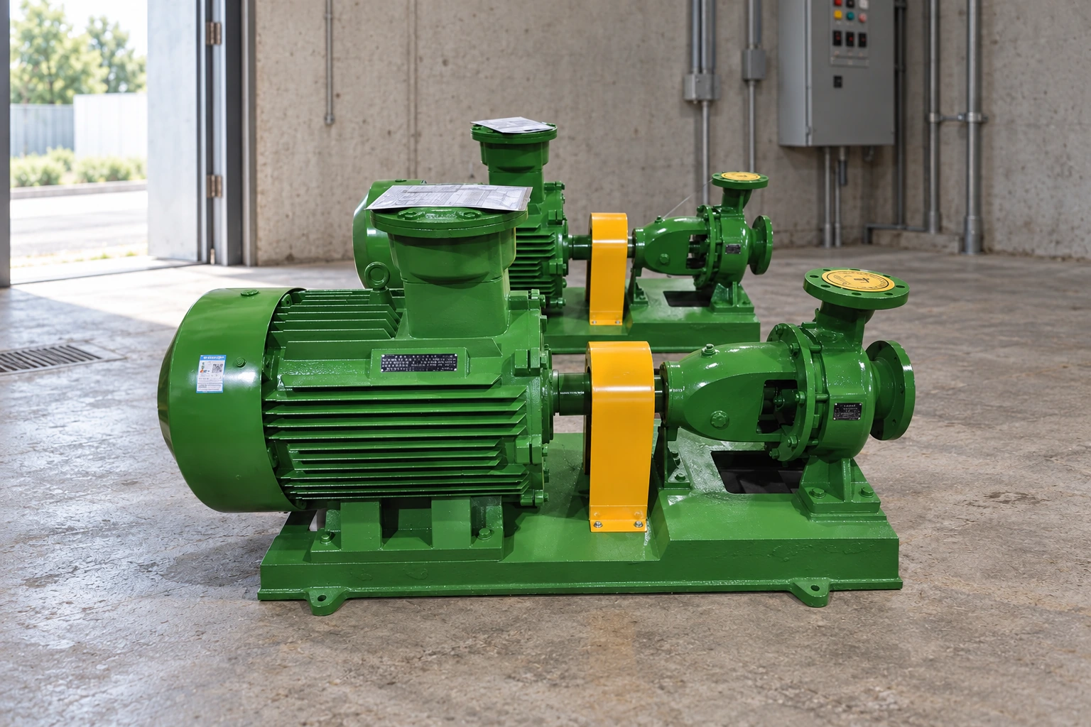
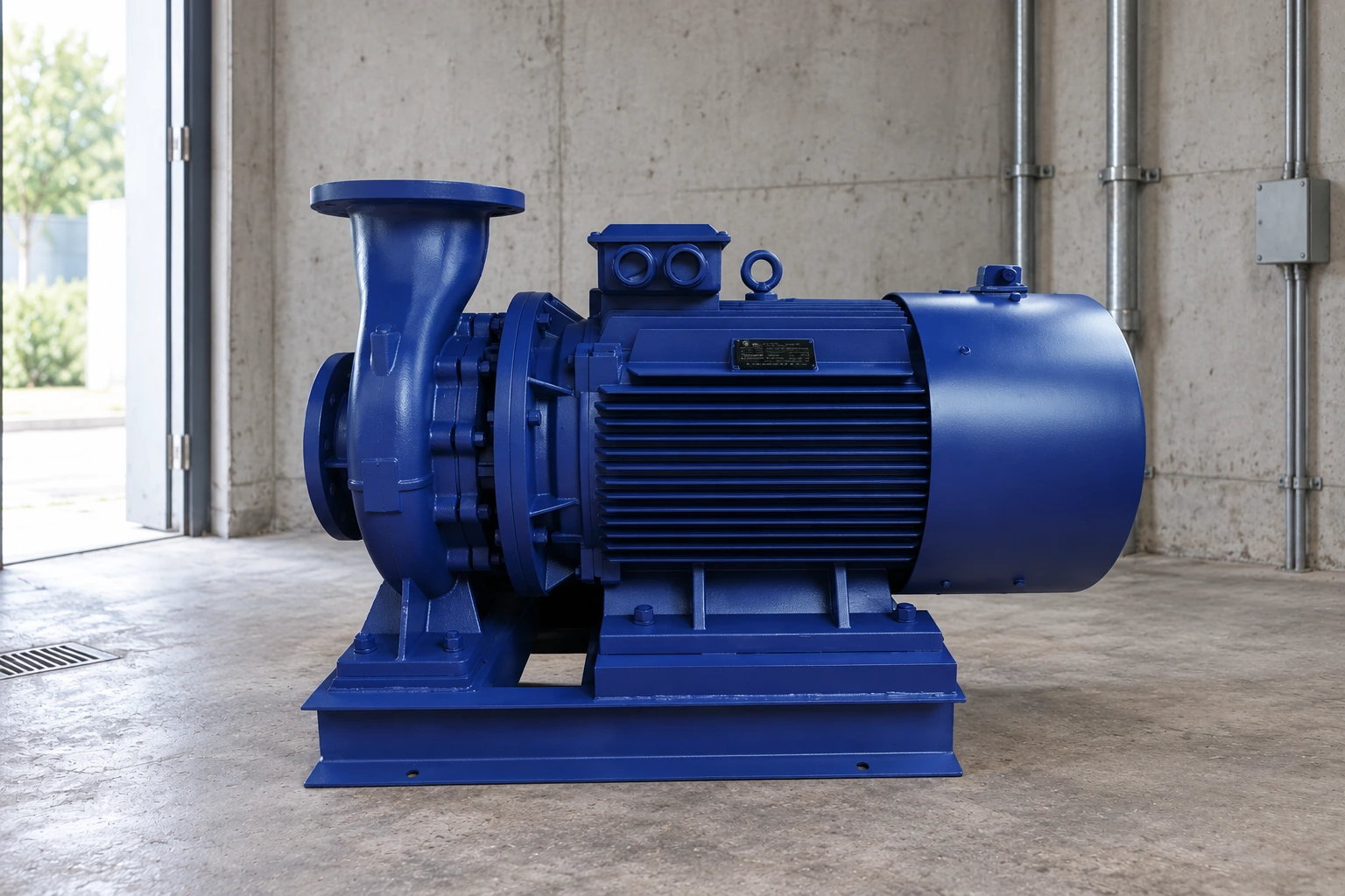
On a CYZ-A self-priming oil-transfer pump, for example, the product category alone cannot establish whether water may contact the process. Obtain the supplied seal specification and fluid requirements before proposing an external utility. The product illustrations here identify pump families; they do not show verified internal flush passages or a completed installation.
Define what may enter the process
First answer a practical question: where will the injected liquid go? If it enters the process, the owner must accept the resulting contamination, dilution and downstream load. A clean-water supply can still be unsuitable for a product that must remain dry, reacts with water, or has a controlled composition. Record the acceptable utility chemistry and the permitted addition as process requirements, rather than treating them as maintenance preferences.
Ask for the process composition, normal operating range, cleaning chemicals and any changes between production campaigns. Identify whether the flush contacts seal faces, secondary seals, piping or other wetted parts. Compatibility must cover the complete contact path. A water treatment method suitable for one duty should not be assumed suitable for another without reviewing the relevant materials and process limits.
The Fluid Sealing Association explains the compatibility and cooling role of external injection in its seal-support discussion for boiler-feed service. That is an application-specific example, not a universal installation instruction. Use it to understand why the injected medium and chamber conditions matter, then obtain the limits for the actual equipment.
Specify conditions at the pump connection
A utility-header reading does not prove that the seal receives the required supply. Pressure losses through filters, control devices, tubing and fittings can change the available conditions at the pump. Shared utility demand can also change during a shift. Place the specified measurement locations on the support-system drawing so a commissioning technician knows exactly which readings are required.
Use consistent pressure references and units. A comparison between a gauge pressure at one point and an absolute pressure at another is invalid until the references are reconciled. Similarly, a pressure difference is meaningful only when the two readings represent the intended operating condition. Do not substitute pump discharge pressure for seal-chamber pressure unless the approved design explicitly permits that relationship.
State the required operating envelope rather than one convenient nominal value. Include starting, normal duty, the expected range of pump operation, stopping and any standby requirement. The responsible engineer should identify the supply behavior needed during each condition. This avoids a system that appears satisfactory during a short test but loses its intended function during a routine operating change.
Build a utility specification that can be checked
The following table is a documentation checklist. It deliberately avoids generic numerical limits because those limits belong to the approved seal and support-system design.
| Specification item | Information to request | Evidence to retain |
|---|---|---|
| Utility identity | Water source, treatment and permitted additives | Utility description and current analysis |
| Process compatibility | Whether injection is allowed and what downstream limits apply | Owner-approved compatibility decision |
| Cleanliness | Particle and deposit-control requirements for the supplied arrangement | Stated acceptance criteria and sampling method |
| Supply pressure | Required range, reference and measurement location | Design value and commissioning readings |
| Supply flow | Required operating range and indication method | Approved setting and observed stable reading |
| Temperature | Inlet range and any required outlet monitoring | Instrument locations and operating records |
| Failure response | Action for inadequate supply or a failed instrument | Approved alarm, stop or operating procedure |
Use the Hydraulic Institute and FSA references above for general context. The completed values must come from the pump/seal documentation and the process review. Mark a missing value as an open item; a blank space should not become an assumed acceptance.
Check cleanliness without inventing a filtration target
The term clean water is too vague for purchasing and commissioning. Ask what contaminants must be controlled, where sampling should occur, how cleanliness will be maintained and how a deteriorating supply will be recognized. Record the source of the water and any treatment equipment that changes its condition before it reaches the pump.
Do not select a filter rating simply because it is common elsewhere on site. The required rating, allowable pressure loss and maintenance method must suit the installed support system. A filter that is too restrictive for the available utility can create a supply problem; a filter without a defined inspection method may conceal progressive restriction. These are design-review questions, not reasons to bypass filtration.
Treat line cleanliness as a separate commissioning task. New or opened tubing can contain debris even when the water source meets its specification. Agree on the approved cleaning, flushing and reinstatement method before connecting the final assembly. Keep the cleaning record with the connection checklist so the person authorizing startup can distinguish verified work from an assumption.
Plan instrumentation and loss-of-supply response
An instrument is useful only if its reading supports a decision. Identify which indication confirms supply availability and which confirms the condition at the seal. A pressure reading by itself should not be presented as a measured flow rate. Where the approved design requires flow measurement, use the specified device and record its units, range and identification.
Define what operators should do if a reading becomes unavailable or moves outside the accepted range. The response may depend on process hazards, the seal arrangement and the plant protection system. Obtain the approved action rather than writing a generic rule that every low reading requires the same response. Never defeat an existing protective function to keep a pump running while investigating the utility.
Make the support system part of the equipment handover. A valve position, regulator setting or alarm value that exists only in one technician’s memory is difficult to reproduce after maintenance. Label the devices according to the plant system and retain the authorized settings in the pump record. Any later alteration should pass through the site’s change procedure.
Commission the arrangement as a complete system
Before work, apply the site’s isolation, depressurization and fluid-handling procedure. Trace the intended line against the approved drawing and verify its connection points. Confirm that the seal, fittings and instruments correspond to the recorded configuration. A commissioning checklist should not authorize pressurizing an unidentified port merely to see what happens.
During the approved test, record utility conditions and pump conditions together. Note whether other utility users are operating, the pump duty, the instrument locations and the time of each observation. A reading without this context can be difficult to interpret when a later shift reports a different result. Preserve the actual observations even if the system needs adjustment before acceptance.
An illustrative handover might say: the specified connection and instrument identities were confirmed, the source analysis was attached, readings were recorded at the designated points, and one unresolved supply variation was referred for review. That record is more useful than an unsupported statement that the flush was checked. It also makes clear whether the equipment has been released or remains on hold.
Separate utility faults from other seal problems
Poor seal performance does not prove that more flush water is the answer. Keep the utility observations separate from seal installation, pump operation, shaft condition and material suitability. If the support system meets its documented requirements, investigate the other evidence before altering the approved settings. Increasing supply without understanding the arrangement can introduce a new problem while masking the original one.
For complementary investigations, see mechanical seal failure on self-priming pumps and mechanical seal versus gland packing. For the broader equipment specification, consult the oil-transfer pump mechanical-seal guide. Those pages address failure causes and sealing choices. This specification checklist focuses on the external utility and the evidence needed before connecting it.
Prepare a clear technical inquiry
Send the equipment identification, seal drawing, fluid composition, operating envelope and available water analysis with the inquiry. Include the utility pressure and temperature ranges at the proposed connection, the route to the pump and any process restriction on water addition. Ask the supplier to identify missing inputs and provide written requirements for the supplied arrangement.
Request the connection schedule, required instruments, operating sequence and acceptance criteria together. This gives purchasing, installation and operations a common reference. A quotation for a pump does not by itself approve the site utility or prove that a particular flush plan is included. Resolve those scope questions before the equipment is commissioned.
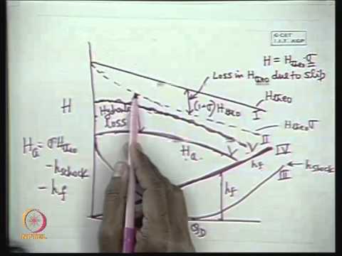
For additional context, the NPTEL lecture below explains centrifugal-pump characteristics. It helps readers understand why pump operating conditions belong in the commissioning record; it is not a seal-flush setting procedure or a substitute for the supplied support-system instructions.
Frequently asked questions
Does every mechanical seal require external flush water?
No. The installed seal arrangement and operating duty determine its support requirements. Identify the ports and obtain the approved drawing before connecting an external source.
Can discharge pressure be used to set the supply?
Only when the approved instructions explicitly define that method. Record the required pressure reference, chamber relationship and measurement points rather than assuming they are interchangeable.
Is drinking-quality water automatically acceptable?
No. Process compatibility, treatment chemistry, cleanliness and temperature still need review. A water supply suitable for consumption is not a complete mechanical-seal utility specification.
Should flow be increased whenever a seal leaks?
Do not change an approved setting solely because leakage is observed. Record the utility conditions, follow the site’s response procedure and investigate the installed seal and pump duty.
What should be included in the final record?
Keep the approved drawing, utility analysis, required ranges, instrument identities, actual readings, unresolved items and release decision together. This allows the next inspection to compare equivalent conditions.