
A jockey pump maintains system pressure against small losses; it is not the main fire-flow pump. When you open a fire pump and jockey pump piping diagram, the first task is to trace two hydraulic paths: the main fire-demand line and the smaller pressure-maintenance loop. For the fire pump cluster overview, see the Fire Pump guide.

Part 1. What Does the Diagram Need to Separate?
A fire pump and jockey pump piping diagram is read as two duties on one system, not as one pump doing everything.
| Hydraulic path | Primary duty | Typical flow scale | Common misread |
|---|---|---|---|
| Main fire pump line | Deliver required fire-flow rate and pressure during a fire event | Full system design flow | Treating jockey size as fire-flow size |
| Jockey pump loop | Maintain static pressure against small leakage and normal drift | Small make-up flow | Assuming jockey can substitute for fire pump |
| Shared discharge header | Connects both paths to the fire protection system | Varies by layout | Ignoring check valve direction between paths |
| Suction source | Supplies both pumps from tank, city main, or reservoir | Site-specific | Mixing suction lift issues into a flooded-suction package |
NFPA fire pump resources describe fire pump systems as engineered arrangements where the main pump serves fire demand and auxiliary equipment supports system readiness. The jockey pump belongs to that auxiliary pressure-maintenance role — not to the primary fire-flow rating.
When tracing a supplier drawing, start at the water source, follow the suction header to the main fire pump, then follow the discharge check valve toward the system. Separately, locate the jockey pump branch, its isolation valves, and how it re-enters the discharge side. If those two paths are not visually distinct on the drawing, ask the supplier for a revised sketch before installation planning proceeds.
Part 2. How Do Main Pump, Jockey Pump, and Controller Signals Relate?
Controller logic only makes sense when overlaid on the hydraulic drawing. The jockey pump is expected to start first when pressure decays slowly from small leaks or temperature effects. The main fire pump starts when pressure continues to fall toward the fire-pump start threshold or when a fire condition demands full flow.
| Signal / event | Typical system response | What the diagram should show |
|---|---|---|
| Minor pressure decay | Jockey pump starts, runs briefly, stops | Jockey suction/discharge valves, return path to header |
| Continued pressure fall | Main fire pump start command | Main pump suction, discharge check valve, controller input |
| Manual or test start | Test header or approved test path | Test line, isolation, drain, flow measurement if specified |
| Power failure on electric driver | Standby diesel start (if designed) | Diesel pump suction/discharge, fuel, controller interlock |
| Controller reset / stop | Pump stop at restore pressure | Sensing line reference and stop setpoint notes |
Exact pressure settings belong to the project specification and controller datasheet, not to a generic article. Hydraulic Institute guidance still applies to the underlying duty: the main fire pump must be selected for the required flow and head at the fire event operating point, while the jockey pump is selected for pressure maintenance flow at the maintenance head.
If the drawing shows both pumps but does not show which controller monitors which pressure reference, that is a review flag. Acceptance testing depends on predictable start order. Installers should not guess controller inputs from a pump label alone.
Part 3. Which Piping Items Should a Buyer Check?
Use the checklist below when reviewing a supplier or package diagram. The goal is to confirm what the pump vendor furnishes versus what the site contractor connects.
| Component | Why it matters on the diagram | Review question |
|---|---|---|
| Suction isolation valve | Service access without draining the source | Is suction isolation shown and accessible? |
| Suction strainer or screen | Protects impeller where required | Furnished by supplier or by site? |
| Main pump discharge check valve | Prevents reverse flow | Orientation and location shown? |
| Jockey pump check valve | Isolates jockey from main flow reversal | Separate check valve on jockey branch? |
| Discharge isolation valve | Maintenance on pump without full drain | On main and jockey branches? |
| Pressure gauges | Commissioning and troubleshooting | Tap locations identified? |
| Test header / test line | Performance verification | Shown with isolation and drain? |
| Main drain / relief path | Safe draining and abnormal pressure route | Drain to safe location noted? |
| Bypass (if any) | Temporary routing during service | Does not bypass required check protection? |
| Pipe connection boundary | Commercial scope split | Which flanges are “by others”? |
Pumps & Systems fire pump coverage repeatedly emphasizes that installation disputes often trace back to missing valve callouts or unclear supplier/site boundaries — not to the pump curve itself. Mark any item shown as “by others” on the supplier drawing and confirm it appears on the engineer’s system layout.
For driver selection context when the diagram shows both electric and diesel pumps, compare diesel fire pump vs electric fire pump before assuming interchangeable piping details. Fuel, ventilation, and controller interlocks add branches that a single-pump diagram will not show.
Part 4. Why Is the Sensing Line Important?
The sensing line is the pressure reference between the fire protection system and the controller. If the tap location, isolation, or damping arrangement is wrong, the controller sees a pressure that does not represent the system — and pumps start or stop at the wrong time.
| Sensing line topic | Practical review point | Common field symptom |
|---|---|---|
| Tap location | Should reflect system pressure the controller is meant to protect | Jockey runs too often |
| Isolation valve | Allows sensor service without disabling the system improperly | Stuck reading during test |
| Snubber or damping | Reduces transient spikes on fast pressure changes | Erratic start/stop during valve operations |
| Shared vs dedicated reference | Controller may use separate taps for jockey and main logic | Main pump starts before jockey resolves minor decay |
| Test connection | Must not defeat the protected reference during normal service | False readings during acceptance |
The diagram should make the sensing path visible enough for the engineer and installer to discuss acceptance testing. It does not replace the engineer’s detail drawing of the sensing assembly.
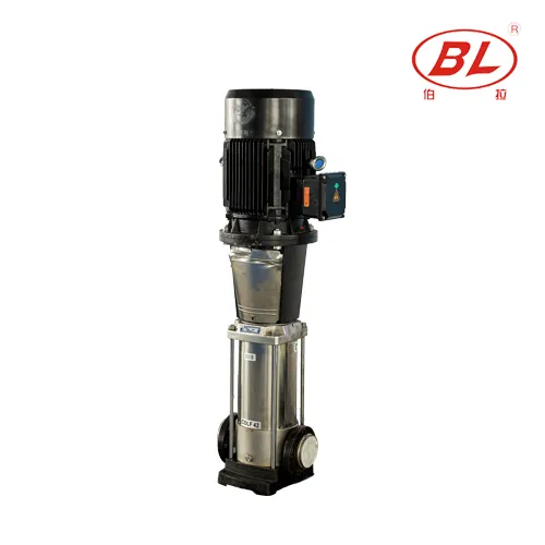
When the jockey pump on the drawing is a multistage maintenance pump such as a CDL(F)-class unit, confirm that the maintenance duty point is documented separately from the main fire pump curve. A jockey selected too large will short-cycle; one selected too small will not hold pressure.
Part 5. How Should EDJ Packages Be Reviewed?
An EDJ package combines electric fire pump, diesel standby fire pump, and jockey pump equipment in one integrated arrangement. The package drawing is a manufacturing and procurement reference — not the full fire-protection engineering drawing for the building.
| EDJ review step | Action | Pass criteria |
|---|---|---|
| Match fire-flow duty | Compare main pump rating to project hydraulic calc | Flow and head align with spec |
| Trace electric and diesel paths | Each driver has suction/discharge isolation | No shared check valve ambiguity |
| Locate jockey branch | Jockey tied to correct header with check valve | Maintenance duty shown separately |
| Controller scope | List inputs, outputs, alarms, and interfaces | Matches spec sequence of operation |
| Fuel and power auxiliaries | Diesel fuel, battery, ventilation, electric feed | Shown or listed as supplier/site split |
| Documentation list | Curves, tests, manuals, spare parts | Matches RFQ document table |
Review the EDJ layout against the building fire-protection design prepared by the project engineer. If the project also discusses sprinkler boosting rather than fire pump approval, route that conversation to booster pump for sprinkler system — it is a different product conversation from fire pump package approval scope.
Part 6. Which BORRAPUMP Products Fit a Diagram Review?
When a diagram review confirms fire pump package scope, these BORRAPUMP catalog routes are common export starting points. Final fit requires verified flow, head, driver, and documentation data.
| Project signal | BORRAPUMP route | Notes |
|---|---|---|
| Integrated electric + diesel + jockey package | EDJ Integrated Fire Pump Set | Compare package drawing to project spec |
| Separate jockey or maintenance pump | CDL(F) Vertical Multistage Jockey Pump | Confirm maintenance duty point |
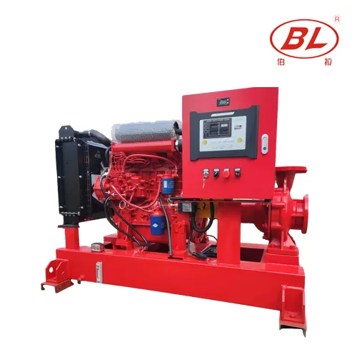
| Diesel standby fire pump driver | XBC-W End Suction Type Diesel Engine Fire Pump | Review fuel, ventilation, and controller interlocks |
RFQ checklist for diagram-based inquiries
| Data item | Why the supplier needs it |
|---|---|
| Required fire-flow and pressure | Sizes main pump |
| Water source type and suction condition | Sizes suction layout |
| Driver preference (electric, diesel, both) | Sets EDJ or split-supplier scope |
| Power supply and diesel fuel assumptions | Electrical and engine auxiliaries |
| Controller and sensing requirements | Matches start sequence |
| Pipe connection sizes and flange standard | Interface boundary |
| Test and certification documents requested | Commercial scope |
| Destination and delivery expectation | Export quotation inputs |
Send completed data through contact Borra. For diesel driver sizing before package review, see how to choose a diesel fire pump.
Fit Boundary
This article teaches diagram reading and purchasing checks. It does not certify a design, approve a fire pump system, or replace project engineering or authority review.
Part 7. What Are the Fit Boundaries?
A supplier piping diagram is one layer in a larger document set. The engineer’s fire-protection layout, hydraulic calculation, and local authority review govern the accepted installation.
Do not treat this article or a vendor sketch as:
- Proof of UL, FM, or NFPA listing for a project.
- A substitute for the engineer’s sequence of operation.
- Permission to omit test headers, drains, or isolation shown in the project spec.
Required certificates, listing marks, and inspection steps must be verified for the exact product model and project jurisdiction before procurement closes.
FAQ
What does a jockey pump do in a fire pump piping diagram?
It maintains system pressure against small leakage and normal pressure drift so the main fire pump does not start for minor losses.
Is the jockey pump the same as the main fire pump?
No. The jockey pump is a pressure-maintenance pump with a much smaller duty. The main fire pump is sized for required fire-flow demand.
Where should the sensing line appear on the diagram?
It should appear on the project and package drawings at the agreed system pressure reference, with isolation and test details defined by the engineer and controller specification.
Can a supplier diagram replace the engineer’s fire-protection drawing?
No. The supplier diagram shows package boundaries and furnished equipment. The engineer’s drawing defines the accepted system layout and authority review path.
What valves should be checked around the fire pump set?
Review suction and discharge isolation, check valves on main and jockey branches, test header isolation, drains, and any bypass or relief paths shown in the spec.
Does BORRAPUMP claim UL or FM approval in this article?
No. Listing or approval must be verified separately for the exact product and project scope.
What data should be sent for a fire pump package quote?
Send required flow, pressure, water source, driver preference, power and fuel data, controller requirements, pipe connections, documentation needs, and destination.
When is an EDJ package relevant?
When the project needs integrated electric, diesel, and jockey pump equipment in one supplied arrangement, subject to engineering review and document verification.