
A booster pump for a sprinkler system can correct a verified pressure shortfall, but it cannot replace missing source flow. First identify whether “sprinkler” means landscape irrigation or fire protection: an irrigation booster is selected from zone flow and pressure data, while a fire sprinkler pump belongs to an engineered fire-protection system with separate equipment and approval requirements.
Contents
- Part 1. Can a Booster Pump Be Used for a Sprinkler System?
- Part 2. Is Low Pressure Really the Problem?
- Part 3. What Flow and Pressure Data Does an Irrigation System Need?
- Part 4. How Do You Size an Irrigation Booster Pump?
- Part 5. Which Installation and Control Checks Matter?
- Part 6. Why Is a Fire Sprinkler Booster a Different System?
- Part 7. Which BORRAPUMP Route Fits, and What Should You Send in an RFQ?
- FAQ
Part 1. Can a Booster Pump Be Used for a Sprinkler System?
Yes—when the water source can supply the required flow and the measured pressure at that flow is too low. The correct equipment and design path depend on what the word “sprinkler” means in the project.
| System | What the pump must do | Selection basis | Approval boundary |
|---|---|---|---|
| Landscape irrigation | Add enough pressure for the largest operating zone | Zone flow, dynamic inlet pressure, nozzle pressure, elevation, and friction loss | Irrigation design, plumbing/backflow rules, electrical requirements, and manufacturer instructions |
| Automatic fire protection | Deliver the hydraulic demand required by the fire-protection design | Hydraulic calculation, water-supply test, fire-pump curve, driver/controller, and system standard | Fire-protection engineer, applicable standard, required listings/documents, and local approval authority |
| Pressure maintenance in a fire system | Replace small losses without serving as the main fire-flow source | System pressure-maintenance strategy and controller settings | Must coordinate with the main fire-pump design |
Part 2. Is Low Pressure Really the Problem?
Before adding a pump, test the system while the problem zone is operating. Static pressure with every valve closed can look healthy even when the source cannot maintain the same pressure at the required flow.
Use this diagnostic order:
- Confirm that the source can continuously supply the largest zone’s flow.
- Measure dynamic pressure near the proposed pump inlet while that flow is passing.
- Check partly closed valves, dirty filters, clogged nozzles, failed regulators, and a restrictive meter or backflow assembly.
- Inspect the mainline and zone valves for leaks.
- Compare pipe size and zone demand; a poorly divided zone can ask for more water than the source can deliver.
- Add a booster only after the remaining deficit is proven to be pressure rather than supply.
The broader guide to what a booster pump can and cannot do explains the same boundary: a booster adds energy to moving water; it does not create a water source.
From the field: “A booster pump won’t create more water.” That installer shorthand from an irrigation controls discussion captures the first sizing rule: available source flow is a hard limit, not a setting to overcome.
Part 3. What Flow and Pressure Data Does an Irrigation System Need?
The irrigation duty point starts with the largest zone that can run at one time. Add the rated flow of its active heads or emitters, then determine the pressure required at the hydraulically worst outlet—not the pressure beside the pump.
| Buyer should measure or confirm | Why it changes pump selection | Common mistake |
|---|---|---|
| Largest simultaneous zone flow | Sets the flow coordinate on the pump curve | Adding every sprinkler on the property even though zones run separately |
| Dynamic inlet pressure at design flow | Shows how much pressure is actually available to the booster | Using static pressure measured with no water moving |
| Required pressure at the worst-case sprinkler | Defines the downstream target | Assuming every nozzle or rotor has the same requirement |
| Elevation from pump to highest outlet | Water loses about 0.433 psi per vertical foot of rise | Measuring horizontal distance as elevation |
| Pipe length and inside diameter | Sets friction loss and affects velocity | Reporting nominal pipe size but not the run length or fittings |
| Meter, filters, valves, and backflow assembly | Each component adds pressure loss | Ignoring the backflow device because it is close to the source |
| Source type and suction condition | Separates a pressurized booster job from a source-lift pump job | Treating a pond, tank, well, and city main as the same inlet condition |
| Maximum allowable system pressure | Prevents damage at low demand or shutoff | Checking only the minimum operating pressure |
The Hunter Irrigation Design Guide calculates design capacity and dynamic pressure from the source, elevation, service line, meter, valves, and downstream losses. University of Florida irrigation guidance likewise ties pipe flow to sprinkler-head demand, operating pressure, pump capacity, and pipe size.
For water, elevation can be estimated as about 0.433 psi lost per foot of rise (approximately 9.8 kPa per meter). Friction grows with flow and must be calculated for the actual pipe and components.
Part 4. How Do You Size an Irrigation Booster Pump?
Select the pump at one operating point: required zone flow and required differential head. The Hydraulic Institute explains that actual operation occurs where the pump curve intersects the system curve, so maximum flow and maximum head cannot be combined as if they occur together.
Calculate the required boost
For a pressurized inlet, use this planning relationship:
Required boost = pressure required at the worst outlet + downstream elevation loss + downstream friction/component losses − measured dynamic inlet pressure at design flow.
Convert the result to head when reading a water-pump curve: 1 psi is approximately 2.31 feet of water head. For example, 20 gpm at 28 psi inlet, a 40 psi outlet target, 7 psi of losses, and 10 feet of rise gives about 23.3 psi of boost, or 54 feet of head. This only illustrates the method; it is not a universal target or model recommendation.
Check the curve and operating range
The shortlisted pump should meet the duty point inside its acceptable operating region, with these checks completed:
- Source flow remains available at the proposed operating point.
- Suction pressure or available NPSH is adequate for the selected pump and temperature.
- Shutoff pressure plus inlet pressure stays below the ratings of the pump, pipe, tank, valves, and sprinkler components.
- The motor and electrical supply match the site.
- The control method can serve both the largest and smallest zones without unstable cycling.
- The manufacturer’s curve represents the exact model, speed, and impeller being offered.
Rain Bird’s self-priming booster-pump performance chart is a useful example of the required format: capacity changes with discharge pressure and suction lift. It should be read as Rain Bird product data, not transferred to a BORRAPUMP model.
If the inlet is an open tank, pond, or canal, suction lift and priming become part of the selection. Review the risks behind booster pump cavitation before treating low inlet pressure as a discharge-only problem.
Part 5. Which Installation and Control Checks Matter?
Controls determine whether a correctly sized pump starts at the right time and remains stable across zones. A timer-based irrigation system commonly coordinates a pump-start relay or master-valve output, while a pressure-controlled installation may use a pressure switch, pressure tank, or variable-speed controller; the pump manufacturer and irrigation designer must confirm the arrangement.
Review these interfaces before installation:
- Pump isolation, service clearance, drainage, and weather protection.
- Inlet and discharge gauges for commissioning and troubleshooting.
- Check-valve location and the pump’s priming requirement.
- Minimum-flow behavior and cycling on the smallest zone.
- Pressure-tank drawdown, if a tank is part of the approved control design.
- Relay/controller ratings and electrical protection.
- Slow valve closure, soft start, or other measures where surge or water hammer is credible.
- Backflow hazard, device type, pressure-loss allowance, and local test/access requirements.
Important: A booster can create backpressure toward a potable supply. Colorado State University Extension warns that an improperly installed lawn-sprinkler pump can drive contaminants back into potable water; a qualified backflow professional and the local authority must determine the protective assembly and pump position for the actual connection. (CSU Extension backflow guidance)
There is no safe universal answer to “before or after the backflow preventer.” Moving the pump changes both pressure conditions and device suitability, while the device itself adds loss that must be included in the hydraulic calculation.
From the field: The question “running frequently, even when sprinklers are off” appears in an irrigation owner’s troubleshooting thread. Treat that symptom as a diagnostic prompt for leaks, a passing zone valve, tank/control settings, or a backflow issue—not as proof that a larger pump is needed.
The general booster pump installation guide covers the broader mechanical sequence; final work must follow the equipment manual and local requirements.

Part 6. Why Is a Fire Sprinkler Booster a Different System?
Unlike a landscape irrigation booster, a fire pump is a life-safety component selected against a fire-protection hydraulic demand. NFPA 20 is titled *Standard for the Installation of Stationary Pumps for Fire Protection* and includes requirements for pump types, drivers/controllers, acceptance testing, and related system elements.
Two pump roles should not be confused:
| Role | Normal purpose | What it is not |
|---|---|---|
| Main fire pump | Supplies the fire-protection design flow and pressure when system demand occurs | A routine domestic or irrigation pressure booster selected only by matching pressure |
| Jockey / pressure-maintenance pump | Replaces small leakage losses and maintains system pressure so the main pump does not start for minor pressure changes | The source of the required sprinkler fire flow |
Important: Similar pressure and flow numbers do not establish fire-service suitability. The project must verify the hydraulic calculation, water supply, pump curve, driver, controller, documentation/listing requirements, system standard, and local approval path. (NFPA 20)
BORRAPUMP’s guide to how a fire pump system works and the BORRAPUMP fire pump guide provide the correct next context. This article does not state that any BORRAPUMP model is UL listed, FM approved, NFPA compliant, or accepted by an authority having jurisdiction.
Part 7. Which BORRAPUMP Route Fits, and What Should You Send in an RFQ?
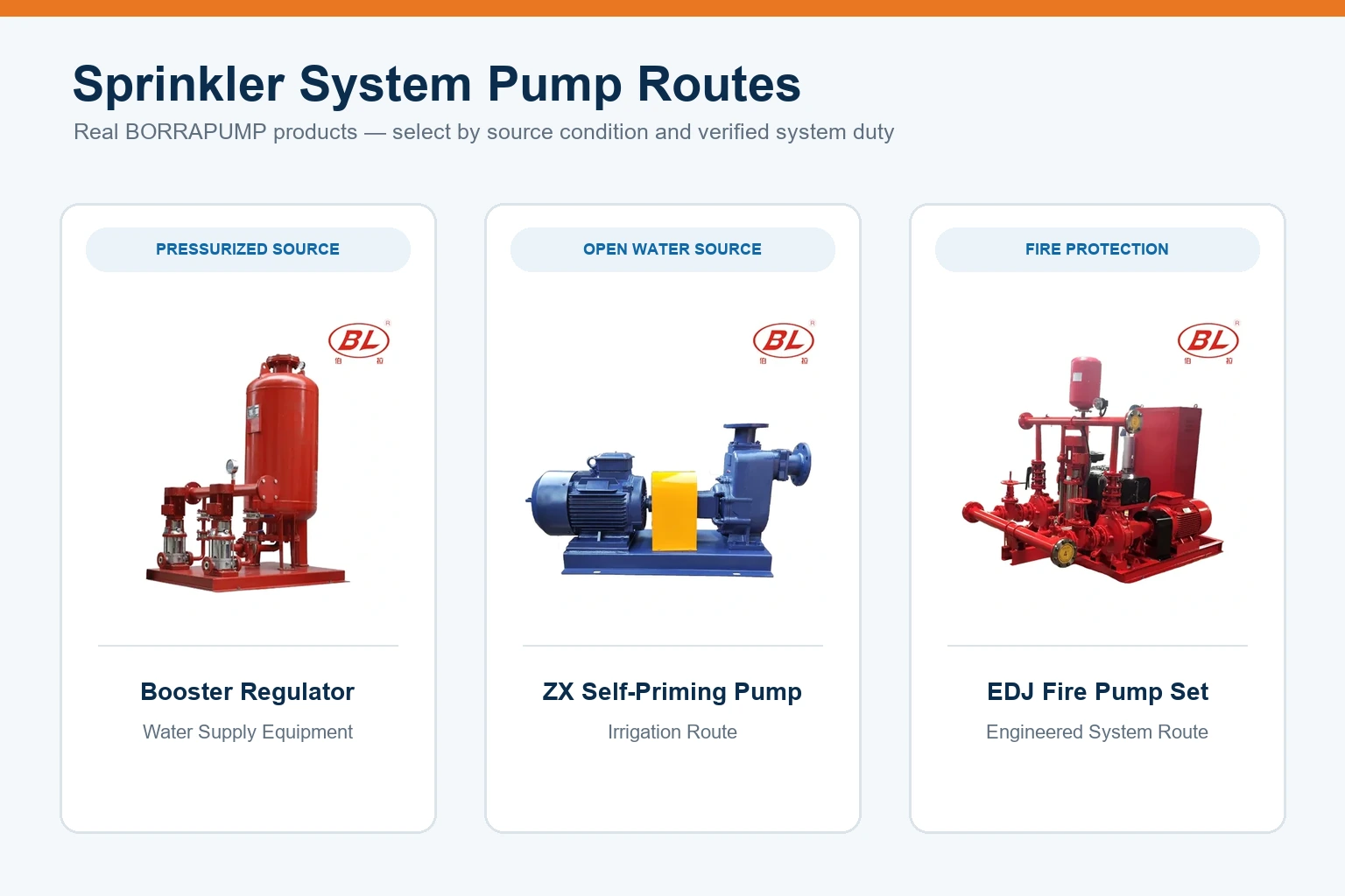
Choose the product route from the source condition and system duty before choosing a model. BORRAPUMP has separate routes for pressure boosting, source lifting, and fire-pump packages; none should be substituted for another without a verified duty point.
| Project condition | Relevant BORRAPUMP route | Why it may fit | Confirmation required |
|---|---|---|---|
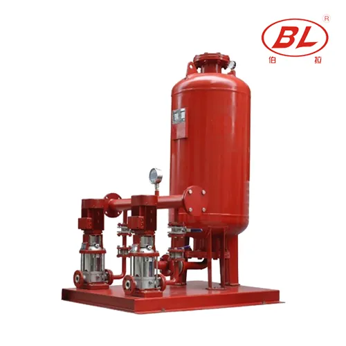
| Irrigation supplied by an adequate pressurized source but lacking pressure | Booster regulator water supply equipment | Packaged booster/regulator route; product page requests flow, head, medium, power, voltage, and site data | Curve at duty point, control method, working pressure, backflow arrangement, and irrigation application fit |
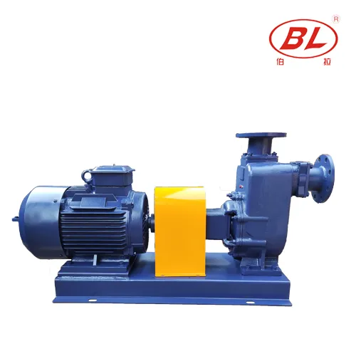
| Irrigation drawing clean water from an open source with suction lift | ZX self-priming irrigation pump | Source-lift/irrigation route with first-priming requirement | Liquid, lift, NPSH, line layout, required flow/head, and model curve |
| Engineered fire sprinkler system | EDJ integrated fire pump set or another verified fire-pump configuration | Fire-system product route rather than a general irrigation booster | Hydraulic basis, driver/controller, required documentation/listings, applicable standard, and local acceptance |
For project matching, send the following data in one package:
- Sprinkler type: landscape irrigation or fire protection.
- Water source and continuously available source flow.
- Largest simultaneous design flow.
- Dynamic inlet pressure measured at that flow.
- Required pressure at the worst-case outlet.
- Elevation, pipe inside diameter and length, fittings, valves, filters, meter, and backflow device.
- Suction lift and priming arrangement, when applicable.
- Control sequence, smallest-zone flow, tank/VFD/relay details, and maximum allowable system pressure.
- Liquid condition, power supply, duty cycle, installation environment, quantity, and destination.
- For fire protection, the hydraulic calculation basis, applicable standard, required listings/documents, driver/controller arrangement, and approval authority.
Fit Boundary
This guide supports diagnosis and RFQ preparation; it does not replace hydraulic design, the pump manual, backflow/electrical review, or local approval. A booster is wrong when source flow is inadequate, the system is restricted or leaking, or zones are oversized, and an irrigation booster is not a substitute for a verified fire pump.
Review the broader BORRAPUMP pump applications or send the sprinkler-system duty data for project matching. The supplier should return a model curve and configuration that can be checked against the same measured duty point.
FAQ
Does a booster pump increase pressure or flow?
A booster adds energy, but operating pressure and flow still follow the pump and system curves. It cannot force an arbitrary pressure and flow outside those curves.
Can a booster pump fix a weak municipal or well-water supply?
Only if adequate flow is available but pressure is insufficient. Otherwise reduce zone demand, improve the source, add properly designed storage, or correct the restriction.
Does a sprinkler booster pump always need a pressure tank?
No universal rule applies. A tank may provide drawdown and reduce short cycling in a pressure-switch system, while a timer/relay or variable-speed design may use a different control strategy. Follow the selected pump/control design and check the smallest zone.
Should the booster pump go before or after the backflow preventer?
Do not choose the position from a generic diagram. Pump placement changes backpressure and negative-pressure conditions, and backflow devices differ in what they protect against. Have the irrigation/plumbing designer, backflow professional, and local authority approve the arrangement.
Why does the booster pump cycle when the sprinklers are off?
Common investigation points include a mainline leak, a zone valve passing water, a check/backflow issue, low tank drawdown, or incorrect pressure-control settings. Isolate the system and test each cause; repeated cycling is a symptom, not a reason to install a larger pump.
Can an ordinary irrigation booster pump serve a fire sprinkler system?
Not by default. Fire sprinkler pumping must follow the project’s hydraulic design, applicable fire-protection standard, required equipment/documentation or listings, controller/driver design, and local acceptance process. Similar pump pressure alone is not enough.
What is the difference between a fire pump and a jockey pump?
The main fire pump supplies the design fire flow and pressure during demand. A jockey or pressure-maintenance pump handles small losses and maintains standby pressure so minor leakage does not start the main pump.
What data should I send to size a sprinkler-system pump?
Send system type, source capacity, design flow, dynamic inlet pressure, required outlet pressure, elevation, pipe and component losses, suction condition, control method, working-pressure limit, power, environment, and documentation requirements. Fire projects also need the hydraulic basis and approval requirements.
References
- Hydraulic Institute Pump FAQs: pump curves and system interaction
- Hunter Irrigation Design Guide: design capacity and dynamic pressure
- University of Florida IFAS: Basic Tips for Designing Efficient Irrigation Systems
- Colorado State University Extension: Home Sprinkler Systems and Backflow Prevention
- NFPA 20: Standard for the Installation of Stationary Pumps for Fire Protection