
A fire pump system combines pumps, drivers, controllers, suction supply, and discharge headers to deliver reliable fire water pressure. This guide focuses on practical hydraulic sizing, application fit, and procurement documentation for export and U.S. project buyers. Where equipment selection is involved, cross-check public specifications on borrapumps.com and confirm project-specific limits with your consulting engineer or AHJ. Section checklists can be reused as RFQ attachments and commissioning handover outlines. As a cluster anchor, this article connects hydraulic demand, system layout, and driver choices so related selection guides stay aligned with the same engineering vocabulary.
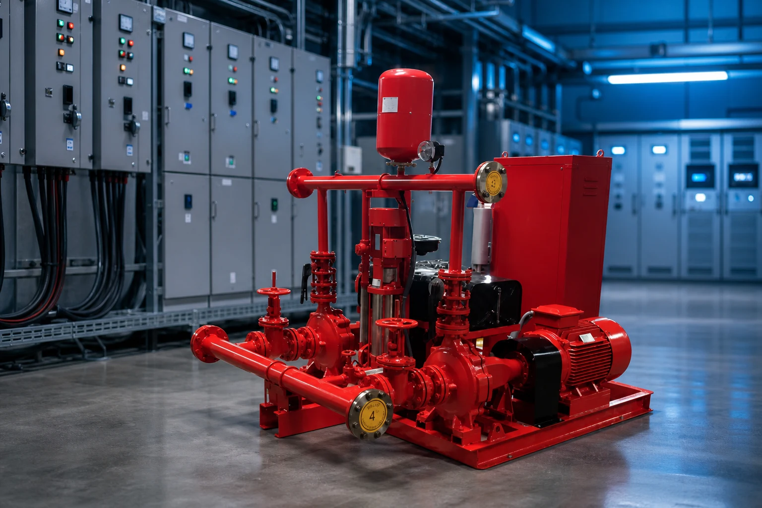
Part 1. Core System Components
Typical packages include main fire pumps, jockey pump, control panel, suction tank or city supply, and test headers.
Project teams should align pump type with hazard classification, water source, and local authority requirements.
Define design flow (GPM or m³/h) and total dynamic head before comparing catalogs—horsepower alone is not a sizing basis.
Review suction lift, water temperature, and entrained air; they affect NPSH margin and priming strategy.
Cross-check related BORRA pump lines against your hydraulic calculation, not marketing peak points.
For export projects, confirm voltage, frequency, enclosure, and local listing expectations early in RFQ.
Request pump curves at the actual duty point—including NPSH data—not only catalog peak efficiency points.
Confirm suction piping, strainers, and priming method before finalizing self-priming versus submersible options.
Define who owns startup, training, and spare impeller or seal kits in the purchase order—not after shipment delays.
Compare quotations on a normalized basis: duty-point head/flow, materials, driver type, warranty, and commissioning scope.
For fire-related packages, coordinate hydraulic calculations with AHJ requirements before locking pump curves.
System-level pump planning should map suction supply, drivers, controls, test headers, and jockey maintenance before SKU selection.
Hydraulic demand calculations—not catalog horsepower—define whether split-case, end suction, vertical turbine, or packaged skids fit the site.
Series fire pump arrangements must reach stable discharge pressure quickly after start demand and restabilize when flow changes.
Test headers, relief paths, and indicating valves should appear on layout drawings before equipment purchase to avoid rework in the pump room.
Electric and diesel drivers impose different room requirements—ventilation, fuel storage, and normal power rules cannot be swapped without redesign.
Owner training should cover weekly diesel tests, jockey alarm response, and when to escalate to the main fire pump contractor.
Retain pump curves, vibration baselines, and controller settings in the O&M file after turnover.
Before adding parallel capacity, verify suction piping, anchors, and electrical feeders can support the upgrade.
Part 3. Field Application and Installation Notes
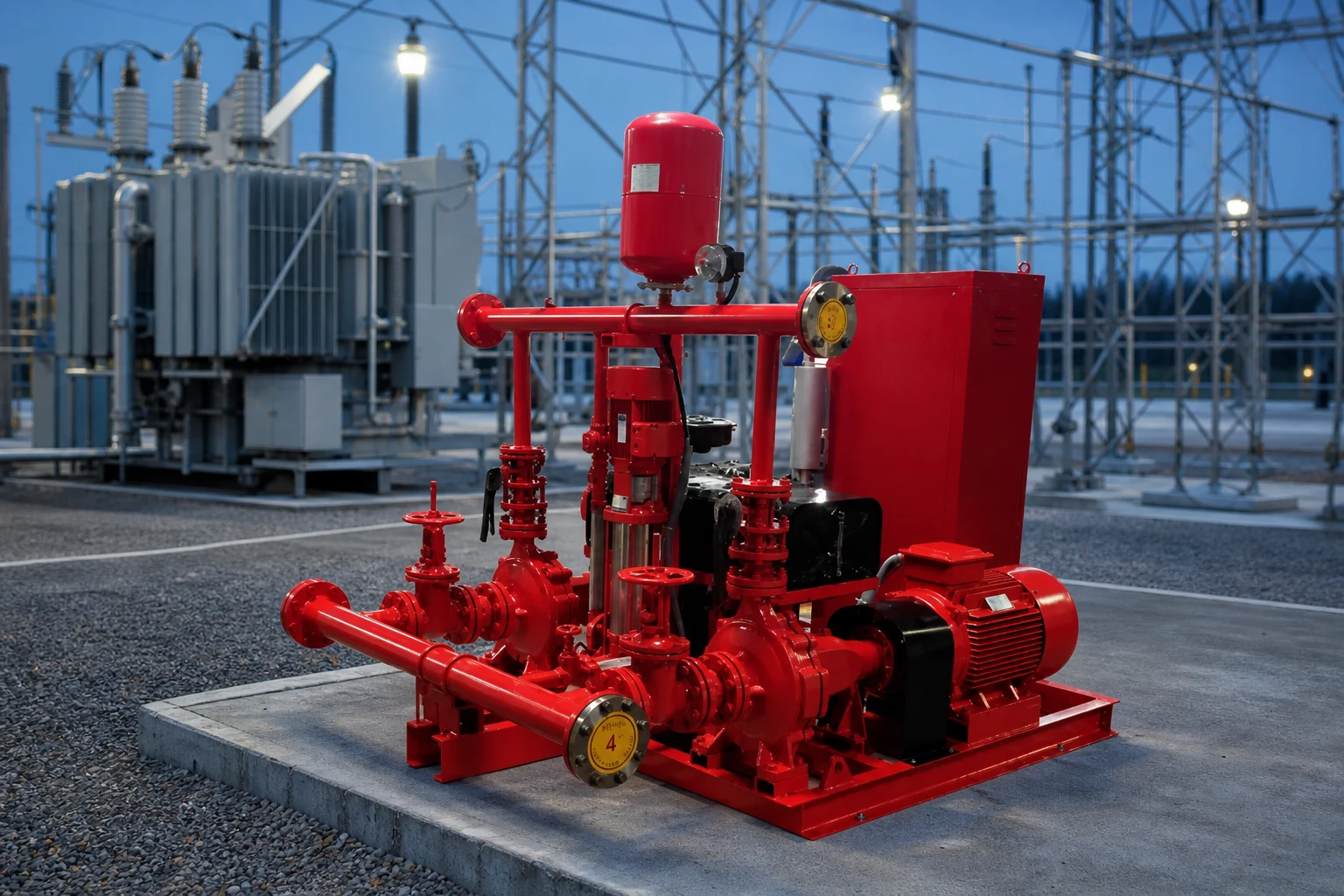
On site, fire pump system selection should be validated against as-built piping, suction entry, and discharge routing—not only spreadsheet estimates.
Verify alignment, coupling guard, and anchor points before wet testing; misalignment accelerates seal and bearing wear.
For temporary dewatering, plan discharge permits, sediment control, and hose routing before mobilizing equipment.
Document startup sequence, alarm setpoints, and responsible operator contacts in the handover package.
When multiple pumps operate in parallel, confirm staging logic avoids short cycling at partial demand.
Export skids should include lifting points, nameplate photos, and spare seal kit part numbers in the O&M binder.
Parallel staging (duplex/triplex) improves redundancy when peak demand exceeds single-pump duty.
Variable speed control can reduce energy use when demand varies across shifts or occupancy.
Align control logic with utility or fire authority requirements before panel build.
Document test header, relief, and isolation valve locations on as-built drawings.
Request pump curves at the actual duty point—including NPSH data—not only catalog peak efficiency points.
Confirm suction piping, strainers, and priming method before finalizing self-priming versus submersible options.
Define who owns startup, training, and spare impeller or seal kits in the purchase order—not after shipment delays.
Compare quotations on a normalized basis: duty-point head/flow, materials, driver type, warranty, and commissioning scope.
For fire-related packages, coordinate hydraulic calculations with AHJ requirements before locking pump curves.
Driver choice (electric vs diesel) follows power reliability rules; export projects should confirm listing and local code early.
Layout drawings should show clearance for impeller removal, controller line-of-sight, and safe fuel or electrical maintenance access.
Retain pump curves, vibration baselines, and controller settings in the O&M file after turnover.
Before adding parallel capacity, verify suction piping, anchors, and electrical feeders can support the upgrade.
| Check item | Why it matters | Typical owner |
|---|---|---|
| Duty-point run test | Confirms curve match | Commissioning agent |
| NPSH / priming check | Prevents cavitation | Mechanical contractor |
| Control alarm test | Ensures fault visibility | Electrical contractor |
| As-built P&ID update | Supports future retrofits | Owner O&M |
Part 4. Documentation and Handover Checklist
Industrial acceptance should not rely on energization alone—documentation proves ratings, safety, and maintainability for the next maintenance cycle.
Use the tables below as a pump RFQ checklist—hydraulic duty, materials, and driver type should be explicit.
For product-specific datasheets, cross-check related BORRA product pages and request missing test data.
When comparing quotations, normalize Incoterms, warranty scope, and included commissioning.
Include lift points, anchor details, and shipping Incoterms in export RFQs to avoid site surprises.
Clarify warranty response, spare parts lead time, and whether factory or local integrator performs startup.
Downstream cluster articles can link back here for shared vocabulary on TDH, NPSH, staging, and acceptance testing.
Retain pump curves, vibration baselines, and controller settings in the O&M file after turnover.
Before adding parallel capacity, verify suction piping, anchors, and electrical feeders can support the upgrade.
| Document / item | Purpose | When to request |
|---|---|---|
| Pump performance curve | Verify duty point, efficiency, and NPSH | Before purchase order |
| Factory test / hydrostatic report | Prove rated head and flow | Contract negotiation |
| Installation manual + wiring diagram | Field assembly and controls | Design phase |
| Spare parts list (seals, impeller, bearings) | Lifecycle planning | Before energization |
| Commissioning checklist | Acceptance at duty point | Before handover |
| Application | Typical pump type | Key selection note |
|---|---|---|
| Building water boost | Vertical multistage / inline electric | Size on peak GPM and TDH; consider VFD staging |
| Fire protection | Split-case, end suction, or vertical turbine | Match NFPA hydraulic demand and suction condition |
| Construction dewatering | Self-priming, submersible, or trailer diesel | Match solids content and portability |
| Municipal wastewater | Non-clog submersible or dry-pit | Confirm solids passage and rag handling |
Part 5. Commissioning, Monitoring, and Long-Term Operations
Commissioning should verify duty-point flow and head on the pump curve, not only motor rotation direction.
Functional tests include priming time, vibration checks, seal flush operation, and control alarm verification.
Log baseline pressure and flow after startup for future troubleshooting comparisons.
Train maintenance staff on lockout/tagout, impeller clearance checks, and bearing lubrication intervals.
Schedule periodic inspection of couplings, seals, and strainers—especially on dewatering and wastewater service.
Keep spare seal kits and critical impeller parts based on lead time, not catalog defaults alone.
Review driver maintenance separately—diesel engines need fuel, battery, and exhaust checks; motors need insulation and thermal history.
After major load changes, re-evaluate whether the original duty point still matches actual operating hours and flow profile.
Pillar and planning articles should be reviewed annually against operating logs, code updates, and site load changes.
Export a PDF snapshot after each major edit so field teams and EPC partners reference the same version during outages and retrofits.
Retain pump curves, vibration baselines, and controller settings in the O&M file after turnover.
Before adding parallel capacity, verify suction piping, anchors, and electrical feeders can support the upgrade.
Recommended BORRA Products
For project support, explore our related product line, solution options, and OEM/ODM capabilities on borrapumps.com.
FAQ
What makes up a fire pump system?
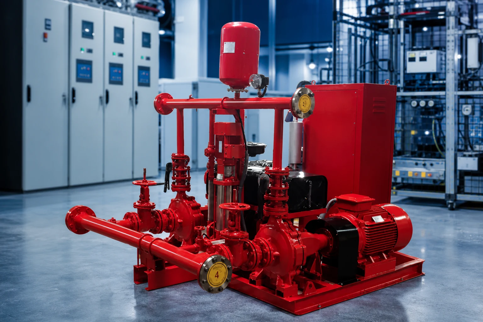
Main pump, driver, controller, suction supply, discharge piping, jockey pump, and test means.
Which standard applies in the US?
NFPA 20 is the primary installation standard for stationary fire pumps.
Why is a test header needed?
It provides a controlled means to flow-test pump performance.
What is churn pressure?
Pressure at zero flow; used when setting jockey and main pump controls.
When are series pumps used?
When single pump head is insufficient; requires coordinated control.
How often must fire pumps be tested?
NFPA 20 requires periodic testing; frequency depends on pump type.
References
Ready to discuss your project? Contact BORRA engineering support with your project parameters and technical requirements.