
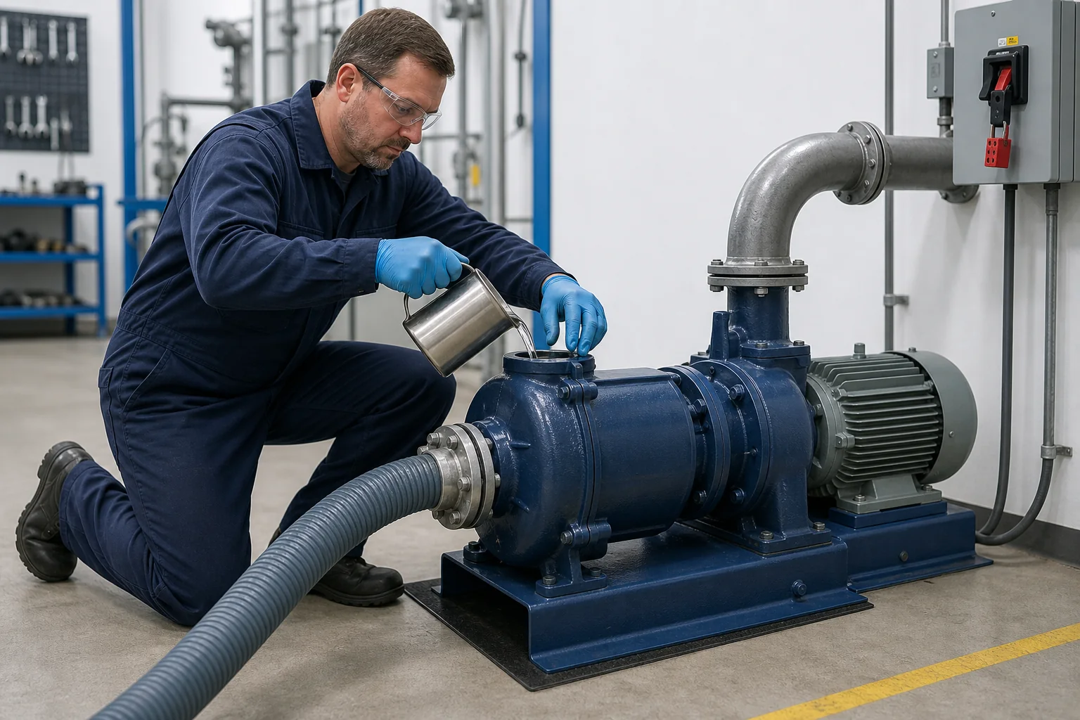
To prime a self-priming centrifugal pump, isolate the equipment, verify the suction system, fill the pump casing with a compatible priming liquid through the designated port, restore the plug, set the valves as the model manual requires, and start the unit while watching for stable discharge. “Self-priming” means the pump can evacuate air from its suction line after the casing holds the required liquid charge; it does not mean the pump should start dry.
The exact sequence and permitted priming time depend on the model. Treat this guide as a planning and troubleshooting framework, then follow the pump manual and site procedure for the final start-up.
Part 1. What self-priming actually means
A self-priming centrifugal pump separates air from a liquid-air mixture and returns liquid to the impeller while the suction line is evacuated. Once liquid reaches the pump and air discharge stops, the unit changes to normal centrifugal pumping.
KSB notes that a self-priming pump still has to be filled with the handled fluid before commissioning. AMT makes the same boundary explicit: a dry casing cannot create the recirculating liquid seal needed for priming, and dry operation can damage the mechanical seal.
The distinction matters during procurement and operation. For the selection rationale behind the pump type, compare the existing guide on why to choose a self-priming pump.
| Term | What it means | What it does not mean |
|---|---|---|
| Initial prime | The casing or self-priming chamber receives the required liquid charge | The suction pipe is always filled manually |
| Self-priming cycle | The pump removes air from the suction line using retained liquid | The pump can tolerate any air leak or lift |
| Re-prime | The pump restores flow after a normal stop if enough liquid remains | The pump never needs inspection or refill |
| Dry-run protection | A separate design or control feature limits dry-operation damage | A standard consequence of the words self-priming |
Part 2. Complete the pre-start checks
Before opening a priming port, stop and isolate the equipment under the site’s approved procedure. Confirm that pressure is relieved and that the liquid is safe to handle. Hazardous, hot, corrosive, flammable, or contaminated liquids require model-specific controls and trained personnel.
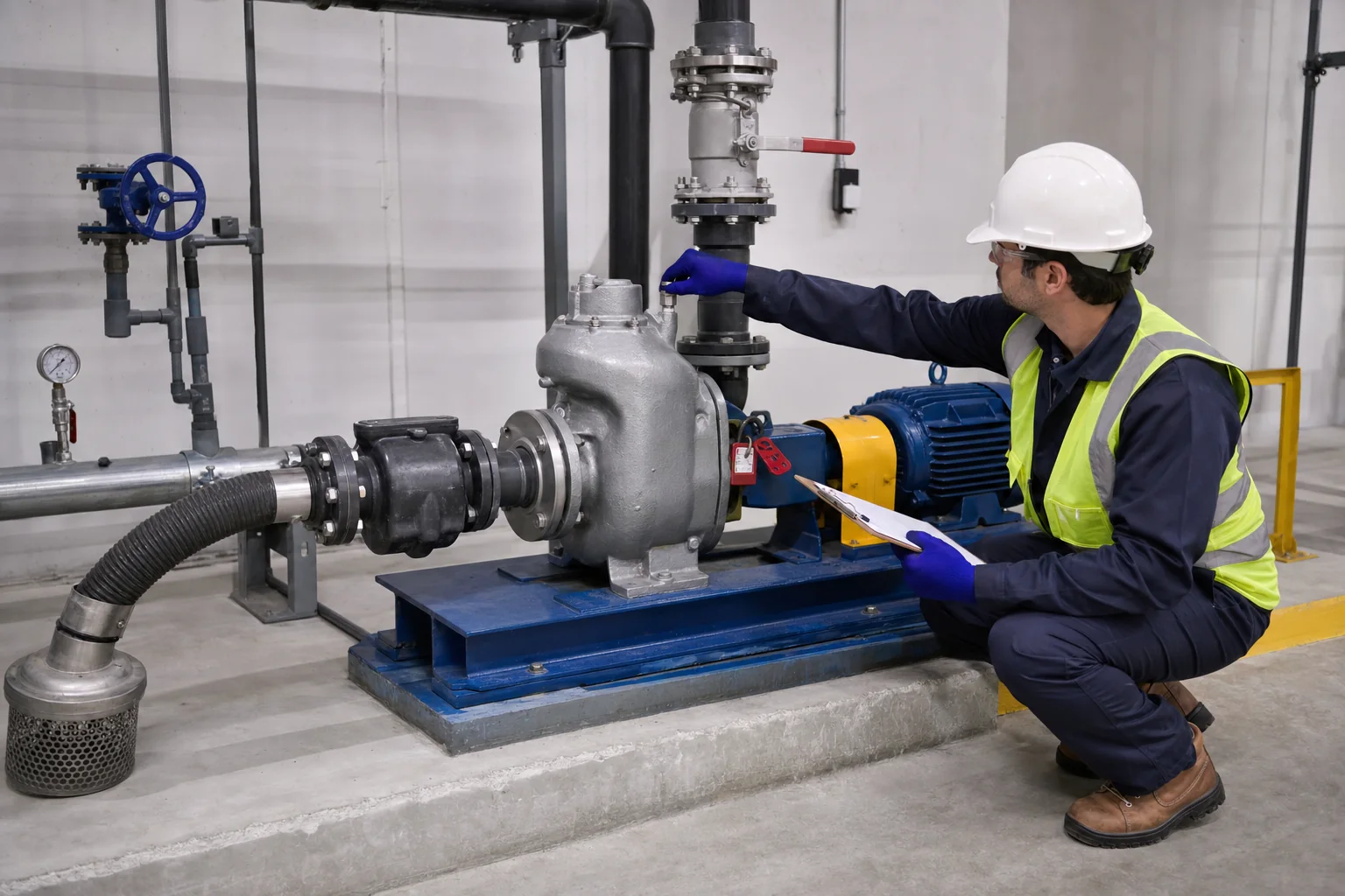
The pre-start review should cover:
- the correct model manual and pump identification;
- compatible priming liquid and required casing fill level;
- suction-pipe diameter, routing, support, and joint condition;
- strainer, check valve, foot valve, isolation valve, and discharge arrangement where fitted;
- correct driver rotation and coupling/guard condition;
- pump mounting, lubrication, seal condition, and drain plugs;
- source liquid level and expected suction lift;
- a safe route for expelled air and liquid at the discharge.
Even a small suction-side air leak can prevent a pump from establishing prime. Threaded joints, flange gaskets, hose clamps, drain plugs, priming plugs, mechanical seals, and valve stems therefore deserve inspection before the operator extends the run time.
Part 3. Fill, vent, start and confirm prime
If the model manual permits manual casing fill, use the designated priming port rather than an improvised opening. The priming liquid normally needs to be compatible with both the pump and the process fluid.
Follow this controlled sequence:
- Isolate and depressurize. Apply the approved electrical and mechanical isolation procedure before removing a plug.
- Open the designated priming point. Inspect the plug, gasket, threads, and sealing surface.
- Fill the casing. Add the specified liquid slowly so air can escape. Stop at the level or volume stated in the manual.
- Reinstall and seal the plug. A leaking priming plug becomes a suction-side air path on many layouts.
- Set the valves. Use the manual’s start-up positions. Do not assume every self-primer starts with the same discharge-valve position.
- Restore power and start. Observe pressure, sound, vibration, leakage, motor current, and discharge behavior.
- Confirm stable pumping. The unit should transition from air-liquid discharge to steady flow within the allowable model-specific priming time.
- Stop if prime is not established. Do not keep the pump running dry while searching for the cause.
Record the time to stable flow during commissioning. A later increase can signal a suction leak, worn internal clearance, lower source level, partial blockage, changed liquid, or a valve problem.
Part 4. Protect priming performance through suction-line design
Priming performance belongs to the pump and the suction system together. A correctly filled casing cannot compensate for a leaking hose, an excessive lift, an obstructed strainer, or a high point that traps air.
Keep the suction route as short and direct as the project permits. Size it from the required duty and allowable losses rather than copying the pump nozzle diameter. Support flexible hose so it does not collapse under vacuum, and seal joints using materials compatible with the liquid.
The source level and elevation also matter. Available atmospheric pressure, vapor pressure, altitude, liquid temperature, friction loss, and pump design limit the practical suction lift. Do not turn a catalogue maximum into a guaranteed field value without checking the complete system.
| Suction condition | Effect on priming | Verification |
|---|---|---|
| Air leak at joint or plug | Pump repeatedly moves air and may never establish liquid flow | Vacuum/pressure test method approved for the system |
| Excessive lift or long pipe | Extends priming time and reduces available suction margin | Elevation survey and loss calculation |
| Blocked strainer | Restricts liquid entry after air evacuation | Safe inspection and differential indication if available |
| Collapsing hose | Reduces flow area under vacuum | Hose vacuum rating and observation |
| High point in line | Traps air and increases evacuated volume | Route review and support correction |
Part 5. Troubleshoot a pump that will not prime
When the pump does not prime, stop it within the limit stated by the manufacturer. Repeated dry starts can heat the retained liquid and damage seals or internal surfaces.
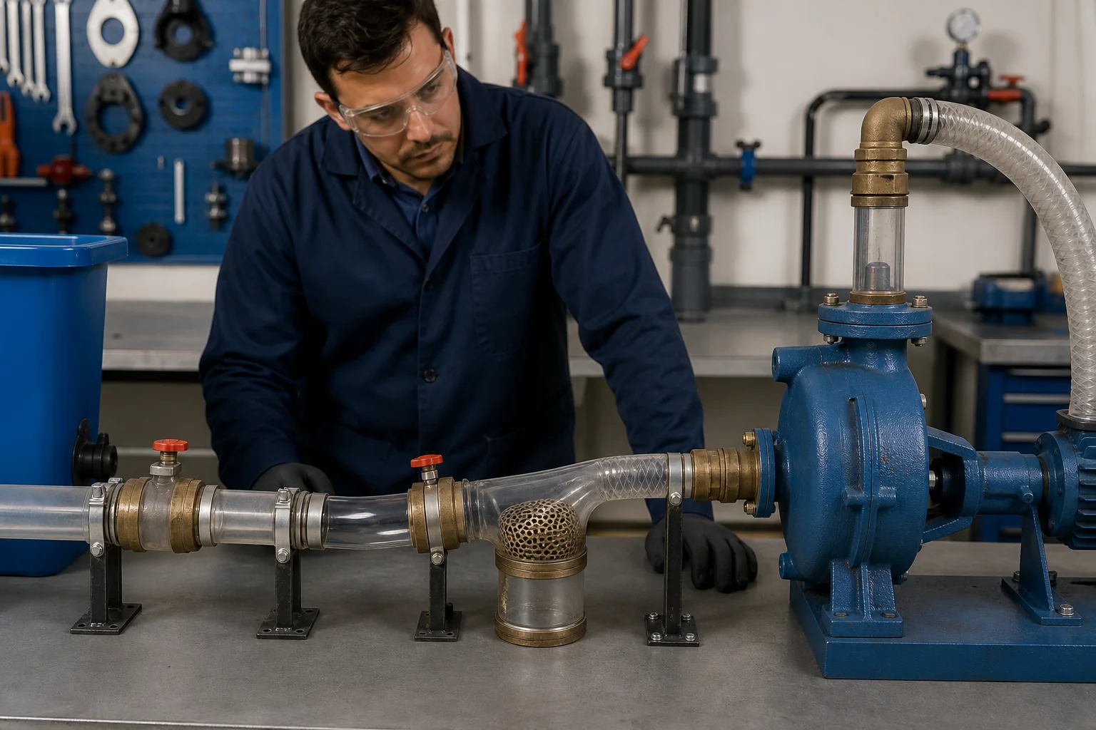
Use a cause-based check instead of adding more run time:
| Symptom | Likely area | Check before restart |
|---|---|---|
| No discharge and casing becomes hot | Missing charge or dry running | Casing liquid level, fill port, seal condition |
| Air continues at discharge | Suction leak or large trapped volume | Joints, plugs, valves, hose, pipe high points |
| Prime is slow after maintenance | Rotation, clearance, valve or reassembly issue | Rotation, wear plate/impeller setting, gasket position |
| Pump primes then loses flow | Source level, vortex, blockage, collapsing hose | Submergence, strainer, hose rating, liquid level |
| Pump loses prime after shutdown | Drain-back path or retained-liquid problem | Check valve, casing drain, plug, internal chamber condition |
Do not bypass guards, defeat dry-run protection, or open a hot casing to speed diagnosis. If the liquid may flash, burn, ignite, react, or expose personnel, escalate to the approved maintenance procedure.
Part 6. Decide when the pump needs re-priming
A normal self-priming design may retain enough liquid for the next start, but retention depends on the casing, valves, drains, seals, and installation. Refill may be necessary after first installation, draining for transport, maintenance, freeze protection, seal work, long storage, or any event that empties the priming chamber.
Recurring manual refill is not a normal substitute for troubleshooting. If the unit repeatedly loses its charge, inspect for leakage, drain-back, valve failure, casing damage, or an installation that cannot retain the required volume.
After shutdown, record unusual noise, leakage, temperature, priming time, pressure, and flow. Maintenance trends are more useful than a single “pump worked” note because changes often appear before complete failure.
Part 7. Send the right RFQ and selection data
Priming reliability begins during selection. A buyer who sends only motor power or connection size leaves the supplier without the suction conditions needed to evaluate the application.
| Buyer should provide | Why it matters | Example | Common mistake |
|---|---|---|---|
| Liquid and temperature | Controls materials, seal, vapor pressure, and safety | Clean water at stated operating range | Writing only “water pump” |
| Flow and total head | Defines the duty point | Required operating point and range | Using maximum flow and maximum head together |
| Static suction lift | Affects priming capability | Pump centerline above minimum source level | Measuring from the wrong reference |
| Suction pipe data | Determines volume and friction | Length, diameter, fittings, hose type | Omitting bends and strainer |
| Solids and viscosity | Changes hydraulic and clogging risk | Maximum particle size and concentration | Assuming all dirty water is equivalent |
| Duty cycle and drive | Affects configuration and controls | Intermittent electric or diesel duty | Giving power without operating hours |
| Site and delivery scope | Supports motor, packing, and documents | Indoor/outdoor, destination, quantity | Mixing selection data with unverified claims |
Include elevation, power supply, portability, controls, test documents, material requirements, and applicable project standards. Ask the supplier to identify any missing data and state whether the selection is preliminary or final.
Part 8. Product Recommendation and Fit Boundary
For a water or irrigation duty that needs a horizontal self-priming centrifugal route, review BORRAPUMP’s ZX self-priming water pump. Its product page explicitly requires priming fluid before operation and asks buyers to match flow, head, medium, power, voltage, site, quantity, destination, and delivery plan.
Projects involving sewage, solids, oil, chemicals, fire protection, or trailer-mounted dewatering should not be routed to the ZX model automatically. Start from the verified BORRAPUMP product range and confirm the liquid, duty point, material, seal, drive, and documentation.
This guide fits general start-up preparation and first-line troubleshooting. It does not replace the model manual, site lockout procedure, hazardous-liquid controls, or engineering review. For the wider set of selection, application, and maintenance topics, see the self-priming pump guide hub, then send the complete suction and duty data through the BORRAPUMP contact page before selection.
FAQ
Does a self-priming pump need to be filled before first start?
Yes. KSB, AMT, and BORRAPUMP guidance all state that the casing or self-priming chamber needs the correct liquid charge before initial operation.
Can a self-priming centrifugal pump run dry?
Do not assume it can. AMT warns that a dry casing prevents correct priming and can cause premature mechanical-seal failure. Use explicit model documentation for any dry-run capability.
Why will a self-priming pump not prime?
Common causes include an empty casing, suction air leak, excessive lift, blocked strainer, collapsed hose, incorrect rotation, wrong valve position, or internal wear. Stop the unit before its allowable priming time is exceeded.
How long should a self-priming pump take to prime?
There is no universal time. Pump design, speed, suction lift, pipe diameter and length, air-tightness, liquid properties, and internal condition all affect the interval; use the model manual.
Does a self-priming pump need a foot valve?
Some self-priming designs operate without a foot valve, including the BORR ZX description. The full system and model manual decide whether a check or foot valve is required.
What data should a buyer send when selecting a self-priming pump?
Send the liquid, temperature, solids, flow, head, suction lift, pipe layout, elevation, duty cycle, drive and power, materials, seal, controls, quantity, destination, and document requirements.