
A self-priming pump diagram earns its keep when the priming path is visible: retained casing liquid, suction-line geometry, air-handling behavior within manufacturer limits, and a discharge connection that can be isolated for service — then verified against the installed model.
Layout reviewers who start at the impeller cutaway alone often miss the suction details that decide whether the machine will re-prime after a stop. This rebuild expands the live article for United States B2B buyers who need a diagram checklist, not a slogan.
Part 1. What the Priming Path Must Show Before Impeller Details
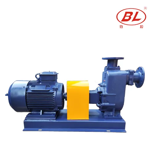
Self-priming performance depends on how the casing retains liquid and how air is separated during prime. A self-priming pump diagram that shows only an impeller cutaway without suction and casing notes is incomplete for field review. Start by locating the retained-liquid path, the suction nozzle orientation, and any manufacturer notes that describe re-prime behavior after a stop.
| Diagram element | Why it matters | Incomplete signal |
|---|---|---|
| Priming chamber / casing | Holds liquid for re-prime | Cutaway without retained-liquid path |
| Suction nozzle orientation | Sets line geometry expectations | Photo-only brochure view |
| Air separation notes | Explains prime behavior limits | Decorative arrows without model basis |
| Discharge nozzle | Defines isolation and piping loads | Missing service clearances |
For vocabulary that sits above the diagram, open the BORRAPUMP Self-Priming Pump guide and the explainer what is a self-priming pump.
Part 2. How Suction-Line Geometry Should Appear on the Layout
Most priming failures begin as suction-side air leaks, high points, or restrictions. The diagram should make joint locations, continuous rise toward the pump where required, strainer or foot arrangements, and supports visible enough to compare with the as-built route.
| Suction item | What to verify | Field symptom if wrong |
|---|---|---|
| Continuous route | No undocumented high points trapping air | Slow or failed prime |
| Joints and gaskets | Airtight route documented | Prime lost overnight |
| Strainer / end arrangement | Matches liquid and design | Starvation or debris entry |
| Supports | Piping does not hang on the casing | Nozzle strain and leaks |
| Length and diameter notes | Match the design basis | Extra losses erode margin |
Suction-lift limits are model-specific. When the inquiry turns into a lift question, continue with self-priming pump suction lift after the layout walk is finished.
Part 3. Where Fill, Vent, and Inspection Access Belong
Find where the manufacturer expects filling and venting, and where covers open for inspection or clearing. Those points belong on the site startup card derived from the installed manual — not from memory of a different model.
| Access point | Document basis | Review question |
|---|---|---|
| Fill connection | Model manual | Can operators reach it safely? |
| Vent path | Model manual | Is trapped air released as designed? |
| Inspection cover | Model manual | Can the casing be opened without pipe strain? |
| Drain | Model / drawing | Where does drained liquid go? |
Important: Do not treat a self-priming pump diagram’s annotated lift figure or priming-time callout as universal. Confirm limits with manufacturer data for the exact model and documented site conditions. (Source: Hydraulic Institute / manufacturer documentation.)
Part 4. How Discharge, Check Valves, and Isolation Are Reviewed
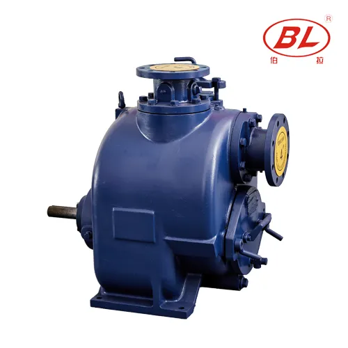
Confirm discharge routing, check valves where the design requires them, and isolation for service. Piping must not impose undocumented loads on the casing nozzles.
| Review stage | Evidence | Owner |
|---|---|---|
| Receiving | Tag and connection orientation versus order | Buyer / receiving |
| Install check | As-built suction route versus drawing | Installer |
| Startup | Prime behavior versus manual baseline | Authorized operator |
| Handover | Exceptions filed with references | Project team |
Pair the diagram checklist with self-priming pump installation checklist when the team moves from layout review into field startup planning.
Part 5. How Diagram Claims Are Held Against Model Data
Lift language, priming-time language, and solids capability are model-specific. Hold any diagram annotation against the manufacturer’s verified data for the exact unit and the liquid actually pumped.
| Claim on a sketch | Ask instead | Evidence required |
|---|---|---|
| Max lift callout | At what liquid, altitude, and suction line? | Model curve / manual basis |
| Fast prime slogan | What baseline time does the manual record? | Startup log versus manual |
| Handles solids | What size and concentration are documented? | Model solids data |
| Universal layout | Which revision matches the install? | Current drawing + as-built |
For self-priming diagrams, note suction-route assumptions, fill/vent locations from the manual, and any as-built deviations already known before comparing offers.
Part 6. Which BORRAPUMP Routes Fit After Layout Clarity
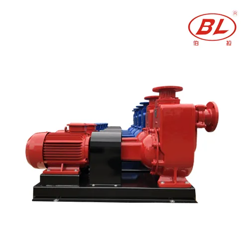
After the layout is clear, discuss clean transfer versus solids-handling self-priming routes with controlled liquid and lift data.
| Duty signal | BORRAPUMP route | Send with quote |
|---|---|---|
| Irrigation / cleaner transfer with surface priming | ZX Self-Priming Water Pump for Irrigation | Vertical lift, liquid description, flow/head with sources, suction line notes |
| Solids-bearing self-prime | ZW Non-Clogging Self-Priming Sewage Pump | Solids description, duty, access plan, documents |
| Dirty drain self-prime | SP jam-less family discussion after duty is clear | Debris type, duty, service plan |
Why not recommend submerged-only units as a substitute when the duty requires surface priming and open casing access: the service model and suction concept differ, and a diagram walk for self-priming equipment will not validate a submersible install.
Send controlled data through contact BORRAPUMP after the layout questions are closed.
Part 7. What Fit Boundaries Apply to Diagram Use
Fits:
- Layout review of surface self-priming installations for contractors and buyers.
- Holding diagram annotations against model manuals before RFQ.
Does not fit:
- Setting a universal suction-lift number for every site.
- Approving an installation from a brochure cutaway alone.
- Substituting submersible design guidance for surface self-priming layout review.
Must be confirmed before quote:
- Liquid description, vertical lift and measurement basis, suction line route, duty flow and head with sources, power data, service access plan, quantity, and destination.
FAQ
What is the most important part of a self-priming pump diagram?
The priming path: casing liquid retention, suction route, and how air is handled during prime, verified against the installed model manual.
Can a diagram provide the maximum suction lift?
No. Usable lift comes from manufacturer data for the specific model at documented site conditions.
Why show the suction line on the diagram?
Air leaks, high points, and restrictions on the suction side are common causes of priming problems.
Where should fill and vent points appear?
Where the manufacturer documentation places them for the model. Copy those onto the site startup card.
Does a self-priming diagram replace the installation checklist?
No. Use it with the installation checklist and the current drawing revision.
What data is needed before selecting from a diagram family?
Liquid description, vertical lift, suction line route, duty flow/head, power, and service plan.
Can solids capability be assumed from a cutaway drawing?
No. Solids passage belongs to verified model data matched to the documented stream.
Does this article approve a priming arrangement?
No. Approval and acceptance follow project documents, responsible review, and verified equipment data.