Self-priming pump suction pipe sizing must balance running friction, available suction pressure, air volume during priming, debris handling, and the selected pump’s inlet requirements. A pipe that is too small increases velocity and loss; a much larger pipe may be difficult to evacuate during prime if it contains a large air volume. The correct size follows the design flow, actual internal diameter, pipe length and fittings, lowest source level, fluid properties, and manufacturer guidance. Airtight construction is equally important: a small suction joint can admit air under vacuum without leaking water outward. Calculate the route, then test it at the worst expected source level before declaring the installation reliable.
Start with the selected pump and source
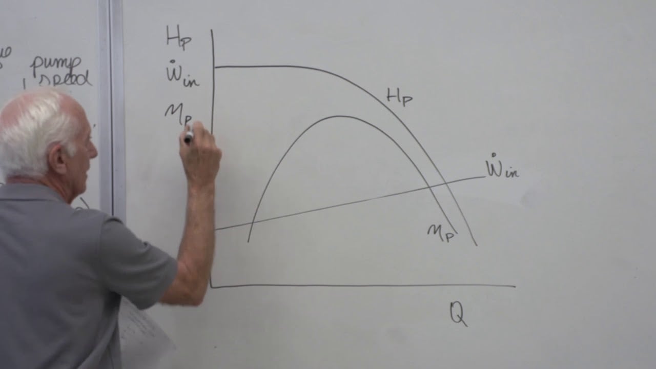
Record the pump model, rated flow and head, allowable priming lift, required suction condition, inlet flange size, liquid temperature, and solids tolerance. Record the lowest water surface, the pump inlet elevation, route length, fittings, strainer, foot valve if any, and expected maximum flow. The BorraPumps centrifugal electric self-priming water pump is the site product reference. Its photograph shows a teal horizontal electric motor, teal self-priming casing, and base, but it does not specify a universal suction-pipe diameter or lift. Obtain the exact model data.
The water-supply booster product range gives the broader application context. A clean-water self-priming unit should not automatically be used for sewage or abrasive slurry. If the source contains solids, choose the pump, strainer, valve, and pipe for that duty first. The suction pipe cannot make an unsuitable pump tolerant of debris.
Calculate velocity from flow and true internal diameter
For a full circular pipe, mean liquid velocity is v = Q/A = 4Q/(πD²), where Q is volume flow in m³/s, D is actual internal diameter in meters, A is internal area in m², and v is m/s. Nominal pipe size is not the internal diameter; wall thickness and lining matter. The formula gives a screening value, not a complete pump selection. Use the expected operating flow, including a high-flow case if multiple pumps or valves can change the duty.
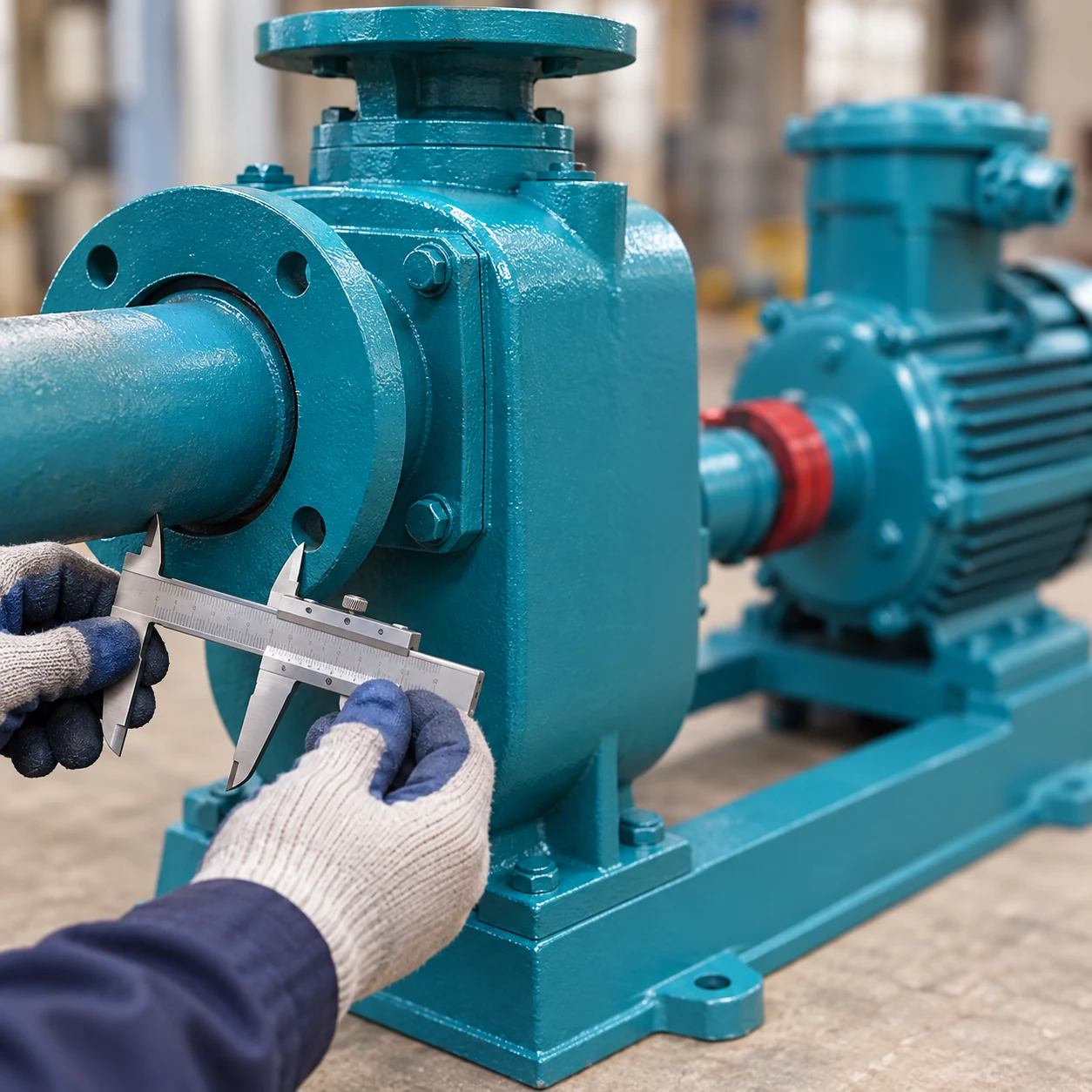
As an illustrative comparison, at Q = 0.010 m³/s, a pipe with D = 0.100 m has a mean velocity of about 1.27 m/s. With D = 0.080 m, the same flow gives about 1.99 m/s. These are computed examples, not universal acceptable limits. Friction depends on pipe length, roughness, fittings, and flow regime; the selected pump’s available suction margin determines whether the losses are acceptable. The University of Florida IFAS centrifugal-pump sizing introduction explains how flow, head, NPSH, and inlet piping interact.
Include every fitting and valve loss
A short straight run can behave very differently from the same nominal diameter with several elbows, a dirty strainer, a foot valve, and a long flexible hose. Calculate friction and minor losses at the actual flow and pipe condition. Include the inlet entrance and any submerged screen. Use data for the chosen valve and strainer rather than assuming every fitting has a negligible loss. Revisit the calculation as the strainer fouls or the source level falls.
The US Army Corps of Engineers Design of Small Water Systems manual treats intake piping and minimum available net positive suction head as inputs to pump selection. The applicable pump-piping standard and the pump maker’s instructions govern a final design; a short article cannot substitute for either.
Check the air-volume tradeoff during priming
When a suction line is empty, the pump has to evacuate its air before water reaches the casing. Air volume for a straight cylindrical section is approximately V = πD²L/4, where L is the air-filled length. Larger D reduces liquid friction but increases air volume roughly with the square of diameter. A pipe twice the internal diameter contains about four times as much air over the same length. This is why an oversized, long suction line may prime slowly even when it runs with low friction after it is full.
For the example above, a 10 m line with 0.100 m internal diameter contains about 79 liters of air when empty; the 0.080 m line contains about 50 liters. Neither volume predicts priming time by itself because the pump’s air-handling rate changes with lift and conditions. The priming-time guide explains how to measure the actual interval. Do not size a suction line solely to make the first start fast if the running NPSH margin becomes inadequate.
| Design check | Undersized or poor route symptom | Oversized or poor route symptom | Verification |
|---|---|---|---|
| Mean liquid velocity | Higher friction and inlet loss | Lower velocity but more pipe cost | Calculate from actual internal diameter |
| Air volume before first prime | Less air but may starve pump | More air to evacuate if line is empty | Calculate line volume and test prime |
| Fittings and valves | Small fittings can dominate loss | Large valves may not open stably at low flow | Use component curves at duty flow |
| Source submergence | Vortex can pull air at low water | Same risk if intake location is poor | Check lowest level and approach flow |
| Joint airtightness | Air can enter without outward water leak | More joints can create more leak points | Vacuum or approved section test |
| Solids passage | Blockage at strainers or valves | Settling risk at too-low flow in some services | Match liquid and equipment design |
The table is a design checklist, not a set of fixed allowable values. Source depth, fluid, pump model, and local rules can change the solution.
Route the pipe to avoid air pockets
Keep the suction route short and direct where possible. A high point above the pump inlet can trap air and delay or prevent prime. A horizontal run should be arranged in accordance with the maker’s instructions so air can move toward an intended vent or pump chamber rather than collect in a crest. If a reducer is needed, select its orientation to avoid an air pocket in the actual pipe geometry. Do not copy a reducer rule from another pump arrangement without checking flow direction and layout.
Support the line independently of the pump flange. A heavy valve or unsupported hose can distort a joint and create an air leak. Avoid sharp bends immediately at the inlet when the maker calls for a straight approach. The existing self-priming suction-lift guide discusses lift limits; the pipe route adds flow-dependent loss to that static challenge.
Prevent invisible suction air leaks
As suction pressure falls below atmospheric pressure, air may enter through a poor gasket, loose threaded joint, cracked hose, valve stem, or priming-port cover. No outward water drip is required. The Hydraulic Institute’s article on unexpectedly low pump pressure notes that negative inlet pressure can hide an air leak and that inadequate submergence can draw in air through a vortex. Inspect the intake as well as the pipe joints.
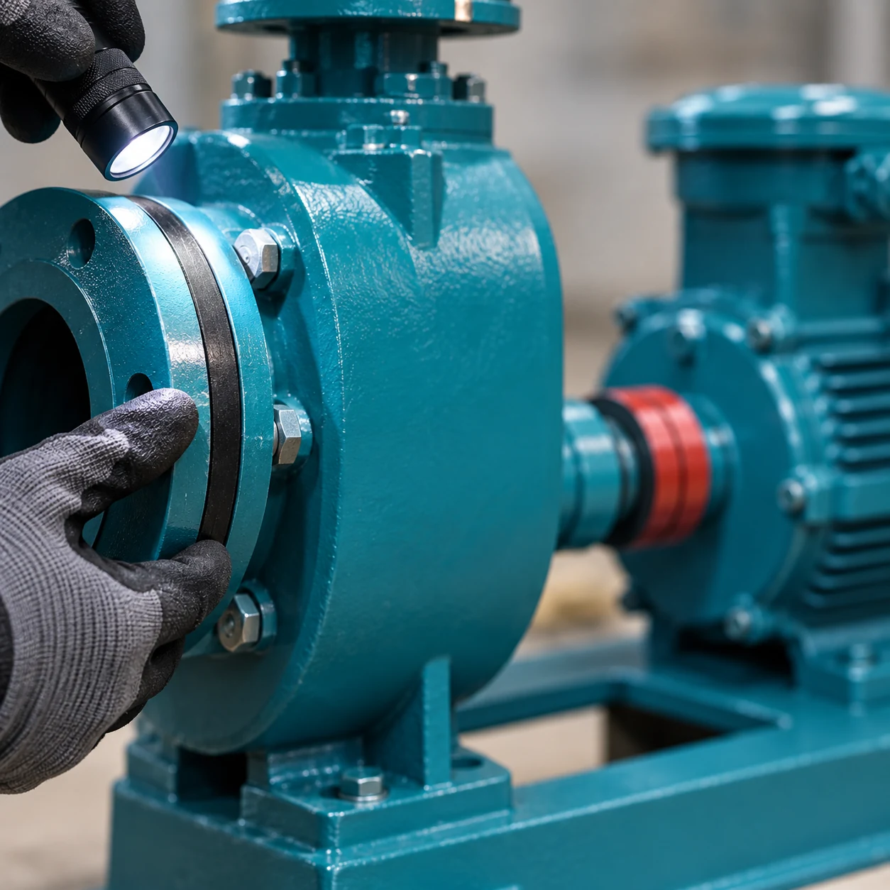
Use gasket materials and joint methods compatible with the fluid, pressure, and vacuum. Confirm flange faces are aligned and pipe supports are installed before tightening bolts. Do not over-tighten a plastic fitting in an attempt to stop a vacuum leak. A vacuum hold or other approved test can localize an isolated fault, but the test pressure must remain within the line’s rating. Flexible suction hose should be rated against collapse under the expected vacuum.
Allow for source-level and temperature changes
The lowest water level, not the convenient commissioning level, governs the maximum static lift. Warmer liquid has higher vapor pressure; higher elevation reduces atmospheric pressure. Both reduce available suction margin. The pump may prime at a test tank and fail at a hot, high-altitude site. Check the maker’s priming-lift and NPSH data for the actual conditions. A foot valve may retain water between starts but adds resistance and can clog, so verify that it improves reliability rather than creating a new bottleneck.
If the source is a pond or sump, provide adequate submergence and spacing from walls and the bottom so the intake does not draw air or sediment. The Hydraulic Institute’s submergence tutorial explains why air-core vortices matter. The final intake geometry may need a detailed design for large flows or unusual basins.
Commission the whole suction system
Record the installed pipe internal diameter, total length, elevation profile, valves, strainers, fittings, and source levels. Fill the casing as required, then time first prime and a restart after a long stop. At normal and peak flow, measure suction vacuum or pressure, discharge pressure, flow, and motor input. Compare the observed suction condition with the calculation. Inspect for bubbles, noise, vibration, and unstable flow. A pipe that passes a static leak check may still draw air when the pump runs at the lowest source level.
Recheck after cleaning a strainer or changing a valve, because the operating point can move. If the pump remains slow to prime, identify whether the limiting factor is line air volume, excessive lift, a leak, source submergence, or the pump’s own air-handling capacity. Document the test conditions so a future operator can recognize deterioration. The self-priming pump troubleshooting checks cover the wider no-flow diagnosis.
What to send a supplier
Send the exact pump model, liquid and temperature, solids, normal and peak flow, lowest and highest water level, proposed pipe material and internal diameter, length, elevation profile, fittings, valves, strainer, and priming requirement. Request a pump curve, NPSH data, permitted suction arrangement, expected priming performance at actual lift, and component-loss guidance. Ask for a drawing showing straight-run and reducer requirements. A correct answer is a checked system, not an isolated pipe diameter.
Frequently asked questions
Should suction pipe always match the pump flange size?
No. Flange size is a connection dimension. Pipe size should be calculated from flow, losses, source conditions, priming volume, and maker guidance.
Can a larger suction pipe hurt priming?
It can increase air volume when the line is empty, even though it reduces running friction. Evaluate both phases.
Why is there no water leak from a suction air leak?
Under vacuum, outside air moves inward. A joint may be dry externally yet admit enough air to disrupt priming.
Can a foot valve fix poor suction piping?
It may retain water between starts, but it also adds loss and can clog. It cannot correct excessive lift, bad routing, or an air leak above it.
Further learning
Cal Poly Pomona’s centrifugal-pump characteristics lecture explains suction head and pump-system curves. It is useful background for checking a suction route, while exact pipe and pump data remain essential.