
Oil pump mechanical seal selection starts with the complete liquid and operating envelope, not the shaft diameter alone. Confirm the oil composition, viscosity at operating and starting temperature, seal-chamber pressure, speed, contaminants and leakage consequences. Then obtain the pump manufacturer’s approved seal arrangement, face pair, secondary seals and installation dimensions. A seal that fits physically can still fail chemically or thermally. For a self-priming transfer package, the selection must also address priming, loss of liquid and shutdown conditions; self-priming does not establish permission to run a mechanical seal dry.
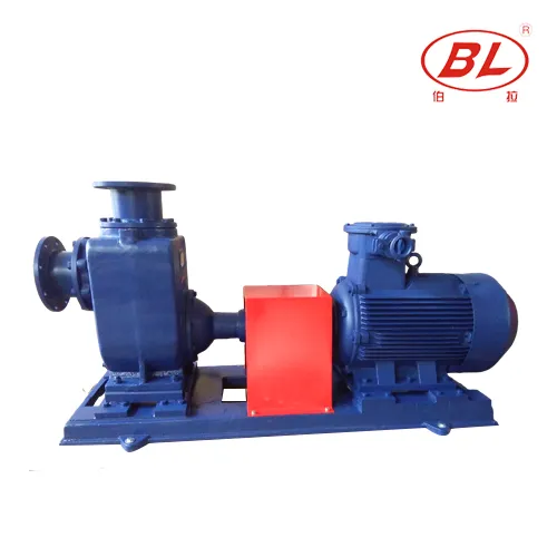
This guide focuses on the seal information needed to specify or replace an oil-transfer pump seal. Start with the broader oil-transfer pump selection guide when the pump type and duty have not yet been decided. The BorraPumps CYZ-A product page identifies the relevant product family; its photograph does not establish a seal material, chemical approval or temperature rating.
Identify which seal is being specified
A mechanical shaft seal controls leakage where the rotating shaft passes through the liquid-containing part of the pump. Its sealing faces work together with secondary sealing elements and supporting hardware. A bearing oil seal has a different purpose: retaining lubricant or excluding contamination around a bearing housing. Ordering an “oil seal” without identifying the location can therefore produce the wrong component even when a diameter appears correct.
Ask for the assembly drawing, parts list and existing seal identification. Record the pump model, serial number, shaft or sleeve diameter, chamber dimensions, mounting features, rotation direction and documented speed. A close photograph of the exterior can help the supplier identify the package, but it cannot reveal the hidden seal arrangement. Avoid dismantling equipment simply to obtain measurements before isolation, drainage and the approved maintenance procedure are arranged.
Describe the oil as a changing liquid
“Oil” is not a sufficient chemical description. Give the product name, safety data sheet, composition information available from the liquid supplier, and any cleaning or changeover fluids that will contact the seal. Diesel-range fuels, lubricants, hydraulic oils and used oils can have different additive packages and contamination. State whether the service changes between products and whether residual cleaning liquid remains before restart.
Record the coldest starting temperature and the normal and maximum process temperatures. Request viscosity at those conditions rather than submitting a room-temperature value alone. Cold oil can change inlet losses, starting behavior and the time required to establish normal liquid circulation. A warm-running condition may introduce a different compatibility or thermal concern. Neither observation by itself identifies a suitable elastomer or face pair.
List water, grit, rust, fibers and other contaminants with the best available sampling evidence. Separate a normal specification from an upset condition. A supplier needs to know whether abrasive contamination is occasional or persistent and whether filtration is proposed. Do not claim that a filter makes contaminated oil suitable until its performance, pressure loss and maintenance arrangements have been reviewed.
Use pressure and temperature at the seal location
The discharge gauge reading is not automatically the pressure acting on the seal faces. Seal-chamber conditions depend on the pump design, operating point and any approved auxiliary arrangement. Submit the required flow and head, suction pressure range, system layout and operating sequence, then ask the pump and seal suppliers to confirm the chamber pressure envelope. Include startup, shutdown and credible blocked-flow or loss-of-suction events for their review.
Temperature also needs a defined measurement location. Ambient temperature, bulk tank temperature and local seal conditions are different quantities. Request the manufacturer’s permitted operating envelope and the evidence supporting it. Avoid applying a material supplier’s standalone temperature range as the complete pump limit: pressure, speed, face loading, liquid behavior and other wetted parts still matter.
Compare materials through documented compatibility
The face pair, secondary seals, metal parts and any springs exposed to the liquid must be considered together. A familiar material abbreviation is not an approval. Ask the supplier to state the exact grade or compound when needed and confirm compatibility with the oil, additives and cleaning fluids over the full temperature range. Where information is incomplete, obtain a written qualification plan rather than substituting a generic chart.
Different face combinations address different friction, wear and chemical conditions. A harder face is not automatically the best choice for every service, and a secondary seal that tolerates the base oil may still be unsuitable for an additive or cleaning chemical. Request the reason for the proposed combination and the operating restrictions attached to it. Keep the approved combination in the spare-parts record so future replacements do not drift to a superficially similar component.
| Auswahlpunkt | Evidence to provide | Required confirmation |
|---|---|---|
| Liquid and cleaning chemicals | Product identification, safety data and changeover sequence | Compatibility of faces, secondary seals and exposed metals |
| Pressure, speed and temperature | Normal duty and startup/shutdown envelope | Approved seal-chamber operating limits |
| Contamination | Samples, particle description and frequency | Wear assessment and any approved support measures |
| Physical fit | Assembly drawing, parts number and verified dimensions | Correct arrangement, setting and installation instructions |
| Leakage consequence | Liquid hazards, location and containment requirements | Suitable containment, monitoring and response plan |
This is an information checklist, not a material compatibility chart. The Hydraulic Institute pump FAQs discuss shaft seals, auxiliary systems, monitoring and maintenance. Final component approval must come from the responsible equipment and seal suppliers.
Choose the arrangement with the whole package in view
Component and cartridge arrangements differ in how the assembly is supplied and installed. Installation convenience does not establish process suitability, and converting an existing design may require changes to space, mounting or supporting equipment. Similarly, a single or dual arrangement must be evaluated against leakage consequences and the available support system. Do not order an arrangement solely because its name sounds more robust.
If the design needs flushing, cooling, quench or a barrier system, obtain the complete approved specification. Identify the fluid source, quality, pressure and temperature requirements, connection points, monitoring, alarm response and maintenance ownership. Introducing an unapproved liquid can contaminate the oil or create a new hazard. An unused connection on the pump exterior is not permission to invent a flush arrangement.
Include priming and intermittent operation
Self-priming describes an operating capability under defined conditions, not an exemption from the seal’s lubrication and cooling needs. Ask how the seal is wetted before starting, what initial fill is required, how air evacuation affects the seal, and what conditions require stopping. Obtain the actual model’s instructions. Do not establish a dry-running allowance from another pump, an internet example or a successful previous start.
Intermittent transfer deserves the same attention as continuous operation. Record the number and length of starts, expected idle periods, whether liquid drains away, and how the package is returned to service. A seal selected only for stable running may not address the transient that repeatedly damages it. For an existing leak, use the separate mechanical seal failure diagnosis guide before ordering another identical replacement.
Control installation and acceptance evidence
Keep replacement parts clean, traceable and in their specified storage conditions. Confirm the approved drawing revision and installation instructions before maintenance. Qualified personnel should verify shaft and sleeve condition, alignment, bearing condition and piping loads as required by the equipment procedure. Replacing a seal cannot correct excessive movement or distortion elsewhere in the assembly.
Define a commissioning record with the supplier: liquid identification, initial filling and venting procedure, operating point, observations, monitoring locations and acceptance criteria. Record leakage in a way that matches the approved arrangement; do not invent a universal “zero drops” or allowable drip-rate rule. Preserve the original test conditions so later changes can be compared fairly. The US Department of Energy pump-systems resources provide broader guidance on evaluating the complete pumping system rather than an isolated component.
Prepare a quotation that can be checked
Send the pump identity, duty envelope, liquid data, drawing, operating sequence and site requirements together. Ask each bidder to return the same information: exact seal arrangement and materials, approved operating limits, auxiliary requirements, installation documents, replacement part identification and unresolved exclusions. A lower price is not directly comparable if one proposal omits a support system or assumes a different liquid.
Keep uncertainty visible. Where the actual CYZ-A configuration or a proposed modification is not documented, request confirmation from BorraPumps before ordering. A comparison of centrifugal and gear pumps for oil transfer can help resolve the pump mechanism first; seal selection should then follow the selected package. Photographs in this article are reference-based illustrations, not evidence of a completed installation, tested seal or stocked spare-part kit.
Further learning: the pump surrounding the seal
The following saVRee educational animation explains the centrifugal pumping mechanism. It supplies context for why the liquid path and operating condition matter; it does not specify the hidden seal or approve an oil-transfer application.
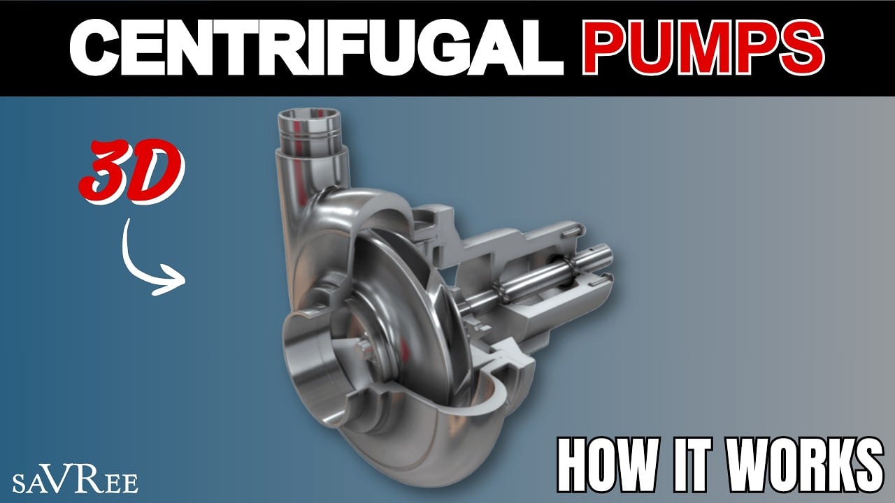
Watch the saVRee centrifugal pump explanation.
Häufig gestellte Fragen
Can I select a replacement seal by shaft diameter alone?
No. Physical dimensions are only one part of the selection. Confirm the approved arrangement, liquid compatibility, pressure, temperature, speed and installation details with the pump and seal suppliers.
Does a self-priming oil pump protect its seal from dry running?
No. Obtain the actual model’s initial filling, priming and stopping instructions. Self-priming capability does not establish an allowable dry-running period for the seal.
Is a bearing oil seal the same as a mechanical shaft seal?
No. They serve different sealing functions and can have very different designs. Identify the location and parts drawing before ordering an item described simply as an oil seal.
Can an elastomer compatibility chart approve the whole pump?
No. A chart may inform a materials review, but the complete package also depends on face materials, exposed metals, pressure, speed, temperature and operating conditions.
What should an oil-transfer seal quotation include?
It should identify the pump and seal, exact proposed materials and arrangement, approved duty envelope, supporting systems, installation documents, spare-parts reference and any unresolved assumptions.