A booster pump duty/standby configuration has one pump sized to deliver the defined duty while another is available to take over if that pump is unavailable. If both pumps must run to meet the design peak, they are duty/assist at that point, not full-duty standby. A three-pump set can combine duty, assist, and standby roles, but the labels depend on each pump’s capacity and the controller’s sequence. Define the duty as flow at a specified head, then test normal, peak, and single-pump-failure cases on the actual curves before calling any arrangement redundant.
Define duty as a hydraulic result, not a label
The design duty is a simultaneous flow-and-head condition. For a domestic-water booster, flow comes from an approved probable-demand calculation and project-specific coincident loads; head comes from elevation, residual fixture pressure, system losses, and available inlet pressure. A pump schedule that says “100 gpm” without head is incomplete. See the apartment flow calculation und building booster head calculation for those separate inputs.
The word duty can also mean the pump currently leading the set. That operational label may rotate daily or after a run-time threshold. It does not by itself mean that a particular pump can supply the entire building. State the capacity requirement explicitly: for example, “125 gpm at 80 ft head with one pump out of service.” Those numbers are an illustration only. The designer must substitute the actual flow and head; a manufacturer’s curve must verify the remaining pump at that point.
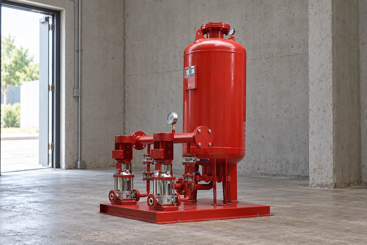
Das BorraPumps booster-regulator water supply package is a possible clean-water packaged solution to review after this capacity and control sequence are defined. The photographed two-pump arrangement does not establish its individual curves, controller logic, or a project-specific N+1 rating. Request that information for the selected model.
Compare the common arrangements
In a one-duty, one-standby pair, either pump independently covers the specified duty; normally one runs at a time, although both may be used under an explicitly different contingency. In a one-duty, one-assist pair, the second pump stages on as demand rises, and both may be required for peak flow. A two-duty, one-standby triple can have two pumps sharing design peak while the third replaces one failed unit—provided any two units actually deliver the peak at the required head. Other arrangements are possible, so capacity must always be read from curves rather than inferred from the pump count.
| Arrangement at design peak | Normal peak operation | One pump unavailable | Full-duty standby only if… |
|---|---|---|---|
| 1 duty + 1 standby | One pump supplies full defined duty | Other pump takes over | Either pump alone meets flow at head |
| 1 duty + 1 assist | Both may be needed at peak | Remaining pump supplies reduced capacity | Not full duty unless one pump alone meets peak |
| 2 duty + 1 standby | Two pumps share peak | Remaining two replace failed pair | Any permitted two-pump pair meets peak |
The table describes logic, not a recommended configuration for every project. A curve check is essential because parallel pumps operate at a common differential head and the individual flow contribution changes with that head. The US Department of Energy pump-systems sourcebook discusses pump/system curves and system-level performance. A nominal “50 gpm pump” and another “50 gpm pump” do not necessarily make 100 gpm at the building’s actual head.
Run the failure-case calculation
Start with the approved peak duty point. Obtain a manufacturer’s curve for one pump at the specified speed and trim. If the arrangement promises full service after one failure, check the remaining pump or pumps at that same flow and required head. Consider the expected inlet pressure range; a failure during a low city-pressure period may be the governing case. If a break tank is used, verify water level and refill assumptions.
Next test the normal low-demand point. A set with two large pumps may cycle at night or operate outside a suitable region if the vessel and controls are poorly matched. A staged set might better match a wide demand range, but the minimum stable flow and motor/drive limits must be checked. Finally, test transition: how quickly will the spare start after a failed lead pump, and what pressure dip is acceptable? These are project requirements, not values that can be assumed from a photograph.
Das Department of Energy pump-systems guidance emphasizes that energy and reliability depend on the complete system and controls. Evaluate real operating points and hours rather than announcing a fixed energy saving from a VFD or a three-pump layout. Purdue University’s operating-point notes explain why the intersection of pump and system curves determines delivered flow.
Explain lead rotation and standby readiness
Alternating which pump is lead can distribute wear and reveal latent faults, but only if the controller starts and monitors each machine correctly. The sequence should define a lead selection rule, start pressure or demand threshold, confirmation of running, assist-stage threshold if used, stop delay, low-inlet protection, and alarm behavior. A standby pump that has not been exercised or whose isolation valve is shut does not provide practical redundancy.
Specify what happens when the pressure sensor fails, the lead pump trips, a drive is unavailable, or normal power returns. Decide whether the controller automatically starts a spare, requires manual reset, or reduces service. The answer may differ for an apartment building, hotel, hospital, or ordinary office property. In a hospital booster selection the continuity and monitoring requirements must be agreed with facility engineers; a nominal spare motor alone is not a complete resilience plan.
Pressure-vessel precharge and effective drawdown also affect short cycling. They are determined from the selected tank, pressure band, water conditions, and minimum operating flow. Do not infer settings or capacity from a catalog photograph. Check isolation valves and non-return valves so a failed or serviced pump does not backflow through its branch.
Distinguish equipment redundancy from system resilience
Two pumps on one skid may still share a single suction line, electrical feeder, controller, sensor, and room. Failure of any common element can disable both. A break tank can itself run empty; a municipal inlet can fall below the pump’s safe operating condition. “N+1 pumps” describes one part of a resilience design, not a guarantee of uninterrupted water under every event.
Map single points of failure for the service level that matters to the owner. Decide whether backup power is required, whether controls have independent sensors, whether maintenance can isolate a pump, and whether a bypass is permitted and safe. Test the actual sequence during commissioning. A facility may accept reduced flow in a failure; if so, document the reduced duty and which outlets remain served rather than advertising full standby.
Für eine hotel, full guest-service continuity may be a commercial goal. In a commercial building, a tenant mix and occupancy schedule may shape the failure case. The configuration follows the owner’s approved requirements and adopted local design rules, not a universal two-pump or three-pump formula.
What to request from a booster-set supplier
Provide design flow and head, typical low-flow range, minimum and maximum inlet pressure, water medium and temperature, duty/assist/standby expectation, permitted reduced-service condition, voltage, control-system and alarm interfaces, mechanical-room dimensions, maintenance constraints, and destination. Ask for single-pump and combined curves at the duty points, motor and drive information, the exact control narrative, and a failure-mode demonstration. Make the pump schedule say how many pumps may be unavailable while the stated service is maintained.
Überprüfen Sie die BorraPumps water-supply booster range for candidate categories, then have the manufacturer match a specific model to the project. Do not assume that every photographed two-pump package has identical capacity, pressure vessel, materials, or controller features.
Common mistakes
The most frequent error is using “standby” to describe an assist pump needed for peak demand. Others include summing catalog maximum flows at different heads, ignoring the minimum supply-pressure case, counting a pump isolated for maintenance as available, and testing only a power-on start rather than a real failed-lead transition. A second pump can improve resilience, but only after the source, piping, power, controls, and maintenance states have been considered.
Häufig gestellte Fragen
Is a two-pump booster set always duty/standby?
No. If both pumps must run at the design peak, the set is duty/assist at that peak. Full-duty standby means the remaining pump alone can deliver the defined flow at head.
Does standby mean the spare never runs?
Not necessarily. A controller may alternate lead duty to exercise both pumps. The capacity requirement remains separate from the daily lead designation.
Is a third pump always an N+1 spare?
No. In a two-duty, one-standby scheme, any two appropriate pumps must meet the defined peak. If all three are required, there is no full-capacity spare at that point.
Was sollte bei der Inbetriebnahme getestet werden?
Test normal peak and low flow, lead rotation, failure detection, spare takeover, low-inlet protection, alarms, and pressure at the controlling outlet under representative conditions.
Weiterbildungen
The NPTEL IIT Kharagpur lecture below explains pump characteristic curves. These curves are necessary to verify the capacity statements in a duty/standby schedule.