
A booster pump diagram is useful only when you know what type of diagram you are reading: a hydraulic layout, a packaged skid concept, a pressure tank arrangement or a control wiring concept.
A good article diagram can explain component order and buyer decisions, but it is not the same as a project construction drawing or a licensed electrical wiring diagram.

Quick answer: Use the article keyword to describe the problem, but size the pump from flow, pressure/head, inlet condition, medium, power supply and control mode. For regulated fire or pressure systems, final acceptance must come from project-specific documents.
Table of contents
- Part 1. Separate the hydraulic path from the control path
- Part 2. What each component does
- Part 3. Reading a packaged booster pump diagram
- Part 4. Wiring notes without overclaiming
- Part 5. How Borra uses diagrams in project discussion
- FAQ
Part 1. Separate the hydraulic path from the control path
The hydraulic path follows water: inlet pipe, valve, pump, check valve, pressure tank branch, pressure measurement point and outlet pipe. The control path follows signals: pressure sensor or switch, controller, motor starter or variable frequency drive, dry-run protection and alarms.
When readers mix these two paths, they often misread a diagram. A pressure tank might be drawn near the pump for space, but its functional connection point matters more than its position on the picture. A controller may be drawn beside the pump, but the key question is which pressure point it reads.
Diagram type
| Diagram | Use |
|---|---|
| Hydraulic layout | Shows water path, valves, check valve and pressure tank branch. |
| Control concept | Shows sensor, controller and motor-control relationship. |
| Packaged skid diagram | Shows what is supplied on the base frame. |
| Construction drawing | Project-specific drawing used for installation approval. |
Part 2. What each component does
Isolation valves let maintenance teams remove or service the pump without draining every connected line. A strainer may protect the pump when the water source carries debris, although it also adds pressure loss and needs cleaning. A check valve prevents reverse flow through the pump after it stops.
The pressure gauge gives a local reading for commissioning and troubleshooting. A sensor or switch tells the controller when to start, stop or vary pump speed. A pressure tank stores a small amount of pressurized water so the pump does not start for every small draw.
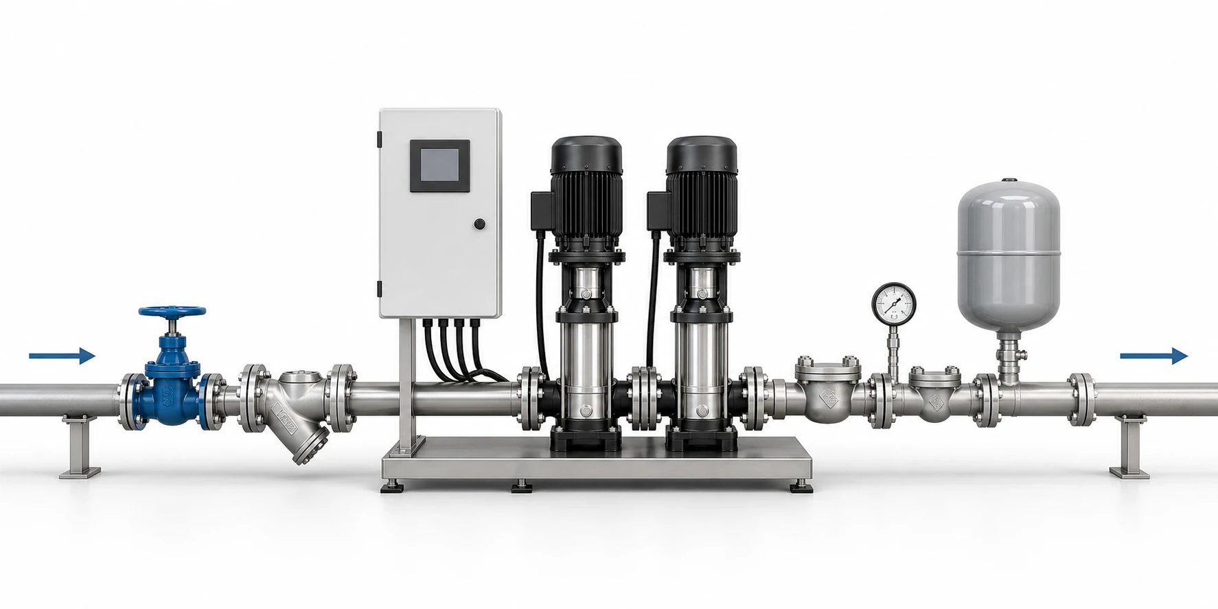
Tip: Read arrows as flow direction, but verify check valve orientation against the supplier drawing.
Part 3. Reading a packaged booster pump diagram
Packaged booster systems often show two or more pumps on a base frame with common suction and discharge manifolds. One pump may serve normal demand while another starts during higher flow or acts as standby. The concept diagram should make the direction of flow, the location of check valves and the pressure measurement point clear.
Do not assume every package includes the same valves, bypass, expansion tank, control cabinet or protection device. Ask the supplier to list the included scope and mark what is by others, especially on export projects where piping, electrical and local compliance boundaries differ.
Component reading guide
| Component | Question to ask |
|---|---|
| Check valve | Does it stop reverse flow in the correct direction? |
| Pressure tank | Is it connected to the controlled pressure side? |
| Sensor or switch | Where is the controller reading pressure? |
| Bypass | Is it for service, emergency flow or both? |
| Controller | Is it fixed speed, pressure switch or VFD control? |
Tip: Ask whether the pressure tank is required for the selected control mode instead of copying a generic diagram.
Part 4. Wiring notes without overclaiming
A blog-level wiring note can say that the controller receives pressure input and controls motor start, stop or speed. It should not pretend to be a final electrical drawing. Voltage, phase, overload protection, grounding, cable size, enclosure rating and local inspection requirements all depend on the project.
If the diagram includes a VFD system, the control logic is different from a simple pressure switch arrangement. VFD systems typically respond to a pressure sensor and modulate speed, while pressure-switch systems start and stop around set points.
Buyer data behind the diagram
| Data | Why it matters |
|---|---|
| Flow and pressure | Defines pump duty. |
| Inlet condition | Avoids cavitation and unstable operation. |
| Power supply | Defines controller and motor options. |
| Scope boundary | Clarifies what Borra supplies and what site contractor installs. |
Important: A web diagram can explain the system concept, but project piping and electrical installation must use the issued project drawing, local code and product manual.
Part 5. How Borra uses diagrams in project discussion
For Borra booster pump inquiries, a diagram should be paired with flow, head, inlet condition, building type, power supply, water quality and installation space. The diagram helps confirm the intended layout, but the quotation must still define the selected pump model, controller scope and supplied accessories.
Relevant starting points include booster regulator water supply equipment, CDL(F) vertical multistage pumps and ISG inline boost pump options. The final package depends on the actual duty point, not the keyword used in the inquiry.

Tip: For packaged systems, request a scope list so valves, controller, sensors and tanks are not assumed.
Relevant Borra starting points
- Booster Regulator Water Supply Equipment
- CDL(F) Vertical Multistage Jockey Pump
- ISG Vertical Inline Boost Water Pump Fire Pump
For a quotation, share the duty point, source condition, power supply, control preference, installation environment and any documentation requirement. That allows the supplier to discuss a package without inventing unverified claims.
Part 6. What to confirm before order confirmation
Before ordering equipment for booster pump diagram, separate the engineering requirement from the commercial request. The engineering requirement is the actual duty point, source condition, liquid type, control method and installation environment. The commercial request is the expected supply scope, packing, lead time, documentation language and after-sales communication path. Keeping these two lists separate helps prevent a low-price quotation from hiding missing accessories or missing documents.
Ask the supplier to state the selected pump model, driver or motor arrangement, controller scope, main accessories, connection size, material assumptions, test documents and items excluded from supply. If a drawing is provided, check whether it is only a concept layout, a general arrangement drawing, or a project-specific document. This distinction is important because buyers often mistake a simple layout image for a final installation drawing.
For replacement or retrofit projects, include photos of the existing pump, nameplate, gauges, pipe direction, tank, controller and available floor space. For new projects, include the design duty, expected operating pattern and any site constraints such as altitude, ambient temperature, power availability, drainage, access route and noise limits. These details reduce revision cycles and help the supplier recommend a practical package instead of a generic pump.
Tip: If the buyer cannot provide a full design duty, mark the offer as preliminary and list the missing inputs clearly in the quotation notes.
FAQ
What does a booster pump diagram show?
It usually shows water flow, pump position, valves, check valve, pressure tank, sensor point, controller and outlet line.
Is a booster pump diagram the same as a wiring diagram?
No. A hydraulic diagram shows water movement, while wiring documentation shows electrical power and control circuits.
Where should the pressure sensor be shown?
It should represent the pressure point the controller must maintain, normally on the discharge or controlled system side.
Why is the check valve important in the diagram?
It prevents reverse flow when the pump stops and helps the system hold pressure.
Can a diagram show a multi-pump booster set?
Yes. It should show common manifolds, pump branches, check valves and the control relationship between pumps.
What should I send with a diagram request?
Send flow, target pressure, inlet pressure, pipe size, power supply, building type and required accessory scope.
Can I install from an online diagram?
No. Use online diagrams for concept understanding and ask for project drawings before installation.
References
Project quotation checklist
- Required flow and target pressure or head.
- Inlet pressure, water source and suction condition.
- Medium, temperature and water quality or solids content.
- Power supply, controller preference and duty cycle.
- Installation space, service access and documentation requirements.
Contact Borra with the project data if you need a pump selection discussion or export quotation.