Low pressure at a booster-pump discharge can come from insufficient inlet pressure, a closed or blocked suction path, air, incorrect rotation, a pump operating away from its curve, a failed control signal, leakage, or a demand that is higher than the original design. Start with a safe pressure and flow record at defined points. Do not increase a setpoint or select a larger pump until the boundary conditions and actual operating point are known.
Define where the pressure is low
Compare the suction pressure, discharge-header pressure, and the pressure at the reported fixture or zone at the same time. Note elevation, open fixtures, operating pumps, valve positions, tank level, and sensor location. A pump-room gauge can look healthy while the upper floor is low because distribution losses or elevation were omitted from the design. Conversely, a low discharge gauge may be caused by a supply-side restriction rather than pump capacity.
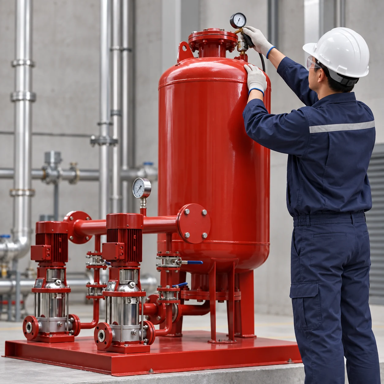
El BorraPumps booster-regulator water-supply package should be matched using the project’s flow, head, inlet pressure, outlet requirement, and control method. Its picture is not a substitute for a model-specific curve or installation manual.
Start at the inlet boundary
Check the incoming isolation valve, strainer, backflow device, meter, flexible connector, and suction pipe. A partially closed valve, clogged strainer, collapsed flexible connector, or inadequate utility pressure can starve every pump. Check for air entering through a threaded joint or a high point that cannot vent. If a break tank is used, verify the actual low water level, refill rate, inlet screen, and low-level protection.
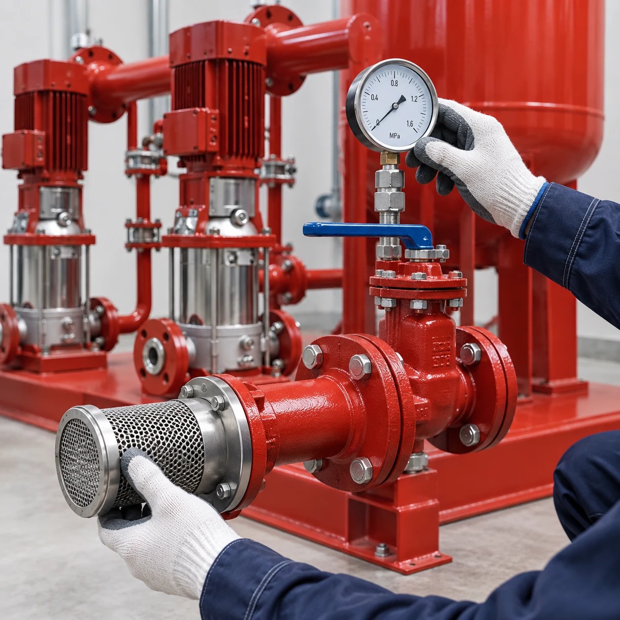
Record inlet pressure while the pumps are running, not only when the system is static. The usable inlet condition can change at peak demand. If the available pressure is below the pump’s required suction condition, increasing discharge speed may worsen noise, cavitation, or damage.
Confirm pump condition and rotation
Verify that the pump is primed, rotates in the marked direction, and has no abnormal noise or vibration. A wrong rotation after electrical work can produce a motor that runs without developing the expected head. Check that the pump is not air-bound and that the suction line is full where the arrangement requires it. Inspect the impeller, wear parts, seals, and strainers according to the manufacturer.
For a multistage or staged set, identify which pump is running and compare the number of active pumps with the control sequence. One pump may be isolated, faulted, or unable to contribute because of a closed discharge valve. The two-pump versus three-pump comparison explains why staging capacity must be checked at the required head.
| Observación | What it can indicate | Verification step |
|---|---|---|
| Low suction and low discharge | Supply restriction or low source pressure | Measure across the inlet path under load |
| Normal suction, low discharge | Pump, rotation, valve, or curve problem | Check rotation, valves, current, and curve |
| Good pump-room pressure, low remote pressure | Elevation or distribution loss | Measure remote point and calculate losses |
| Pressure falls as flow rises | Restrictive pipe, undersized pump, or inlet limit | Record flow and compare with system curve |
| One pump has no contribution | Isolation, check valve, fault, or control issue | Check status and differential pressure |
| Pressure fluctuates | Sensor, air, vessel, or unstable control | Compare independent gauge and signal trend |
Use the table to organize measurements; it does not replace isolation, lockout, or the selected equipment instructions.
Check the discharge path and demand
Inspect discharge isolation valves, check valves, pressure-reducing valves, filters, and the header. A stuck check valve or an incorrectly set pressure-reducing valve can limit delivery. Look for a hidden leak, a newly opened branch, irrigation demand, or a fixture using more flow than assumed. Compare the current demand profile with the original calculation.
El apartment booster flow guide explains how a fixture inventory becomes a probable design flow. If actual demand exceeds the selected duty, low pressure is a sizing issue rather than a simple setting issue.
Verify the pressure sensor and controls
Compare the controller’s displayed pressure with a calibrated gauge at the same point. Check for a blocked sensing port, closed isolation valve, incorrect range, broken cable, or a sensor installed where turbulence dominates. A VFD may be running at a low limit, responding to the wrong sensor, or stopping because of a false alarm. The sensor placement guide covers the difference between a local header measurement and a remote critical-point signal.
Review minimum and maximum speed, staging thresholds, ramp times, sleep mode, and restart conditions. Do not bypass low-inlet or high-pressure protection merely to obtain a higher gauge reading.
Use a consistent head calculation
Calculate elevation, required residual pressure, pipe and fitting losses, device losses, and usable inlet pressure at the same design flow. The booster-pump head calculation guide provides the equation and boundary checks. Compare the result with the pump curve at the actual speed and number of pumps. A catalogue maximum head at zero flow does not prove the pump can deliver the required flow.
Commission after correcting the cause
After repair, record suction pressure, discharge pressure, flow if available, active pumps, motor current, sensor reading, tank level, and the time of the test. Check low, normal, and peak demand. Test lead rotation, pump failure, sensor loss, and restoration of power. Confirm that the remote fixture or zone—not only the pump-room gauge—meets the design condition.
Separate a local complaint from a system-wide fault
Ask whether low pressure occurs at every outlet, one floor, one branch, or only during a short peak. A single branch may have a closed valve, blocked aerator, pressure-reducing valve, or local pipe restriction. A whole-building problem points more strongly to inlet conditions, pump capacity, control, or a common header. Measure at the complaint point and at the pump boundary before changing equipment.
Do not ignore high pressure elsewhere
Increasing a booster setpoint to improve an upper floor can raise pressure at lower floors or downstream equipment. Review pressure zones, relief devices, and pressure-reducing valves. Record the highest pressure as well as the lowest. The safe solution may be zoning, a remote sensor, or a different pump arrangement rather than a single higher setpoint.
Check instruments before declaring a pump fault
Gauges can be damaged, out of calibration, or connected to different elevations. Compare instruments at the same point with a calibrated reference and record whether the reading is static or flowing. A pressure sensor range that is much wider than the operating band can make a small signal error look like a large control problem. Check the display, signal, and physical gauge together.
If the pump develops pressure with the discharge valve closed but not at flow, the issue may be a system restriction, insufficient inlet, or pump curve mismatch. If it cannot develop pressure even at low flow, inspect rotation, priming, impeller condition, and the isolation valves. Treat these observations as diagnostic clues and confirm them with safe measurements.
Use the result to prevent recurrence
Once the low-pressure cause is corrected, update the pump schedule, valve list, sensor record, and maintenance notes. State the normal inlet and discharge ranges and the conditions that trigger an investigation. This prevents a future technician from treating a known design limit as a sudden failure.
Check seasonal and utility changes
Utility pressure, irrigation use, storage-tank level, and occupancy can change by season. A system that meets the morning peak in one month may be low during a dry-season demand peak. Record the date, weather or utility condition when relevant, and the building load during troubleshooting. If the source condition is outside the original design, the responsible engineer may need to revise the duty or add a defined operating limit.
Check the highest and lowest pressure
The final record should show both the lowest reported service pressure and the highest pressure elsewhere in the zone. A correction is complete only when it improves the complaint without creating an overpressure condition at another fixture or floor.
Engineering sources
El US Department of Energy pumping-system sourcebook y Washington State University total dynamic head calculator provide general head and loss concepts. Check the project’s real components and adopted plumbing requirements before changing a pump.
Preguntas frecuentes
Can I solve low pressure by raising the setpoint?
Not safely without checking pump curve, pipe losses, lower-floor pressure, vessel, and protective limits. The cause may be on the suction side or at the sensor.
What if pressure is good with one fixture but low with several?
The system may be limited by pump capacity, inlet pressure, pipe loss, or a staged control sequence. Measure flow and pressures under both conditions.
Why is suction pressure important?
The pump can only add the head its curve permits from the available inlet condition. A restricted or low-pressure inlet can reduce delivery and create cavitation risk.
What information should I send a supplier?
Send design and peak flow, required head, inlet range, residual pressure, pipe and valve information, water condition, voltage, control method, and the observed low-pressure measurements.
Further learning
The NPTEL IIT Kharagpur lecture on pump characteristic curves is useful background for understanding why the installed system can behave differently from a catalogue point. It is educational material, not a substitute for the selected pump manual, project calculations, or local code review.