
Select a borehole pump diameter by checking the smallest usable inside diameter of the finished well against the maximum outside envelope of the complete pump assembly. Include the motor, cable guard, joints, riser fittings and any cooling sleeve that must travel down the well. Then verify the selected hydraulic duty, motor cooling arrangement and a practical retrieval path. A nominal casing label alone cannot establish a safe fit. The clearance must come from the selected equipment drawings and a documented well survey, rather than a universal allowance copied from another installation.
This guide concentrates on physical fit and service access for agricultural and commercial water wells. For the broader relationship between flow, pumping water level and required head, start with our deep well pump selection guide. Diameter is one selection constraint; it does not replace the pump curve or the well’s sustainable yield.
Separate borehole diameter, casing diameter and pump diameter
The drilled borehole is the opening made during construction. A casing or liner installed inside that opening has its own wall thickness and internal dimensions. The pump must pass through the finished opening, not the original drilling diameter. A nominal casing size can therefore mislead a buyer who compares it directly with a catalog’s nominal pump size.
Pump diameter may also describe only one part of the equipment. A hydraulic stack, motor, cable protector and discharge fitting can have different external dimensions. Ask the supplier which measurement the advertised size represents. Obtain the maximum assembled envelope, with the accessories required for the actual installation included, before treating a pump as a candidate.
Penn State Extension’s well construction guidance connects casing selection with intended pumping demand before drilling. Its example sizes provide construction context, not guaranteed clearance for every commercial pump. For an existing well, measured condition and equipment drawings remain the acceptance documents.
Survey the narrowest usable passage
Start with the well log, casing specification, screen description, installed depth and maintenance history. Record the known internal diameter and any liner, repair sleeve, reducer or change in casing. Keep the surface opening, deeper restrictions and intended pump setting separate in the survey. A wide opening at the wellhead does not prove an uninterrupted passage to the installation depth.
Ask the well contractor how straightness and access will be verified without damaging the well. An older casing may contain deposits, distorted joints or a repair section that changes the available opening. Where uncertainty remains, a suitable inspection or contractor-approved checking method is more useful than ordering a smaller nominal size by guesswork. Do not force a pump past an obstruction.
Use the smallest verified usable diameter in the fit review. Describe the survey method, its depth coverage and its limitations. If only the upper casing has been checked, state that explicitly. The purchasing decision should remain conditional until the passage that matters has been assessed.
Check the full equipment envelope
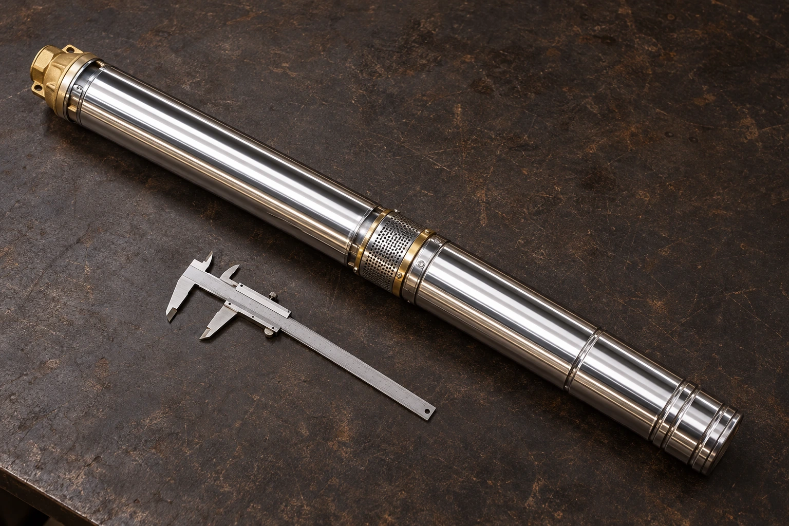
Prepare an assembly list before comparing dimensions. It should identify the hydraulic unit, motor, discharge connection, cable protection, drop pipe coupling and any installation accessory that enters the well. Review the widest element and the position where it occurs. Several individually suitable components can still create an unsuitable combined assembly.
Our QJ deep well pump product page provides the relevant product family for an irrigation enquiry. The photographs show the external cylindrical arrangement. They do not establish a model’s diameter, clearance, permissible sand content or cooling requirements. Request the selected model’s drawing and operating documents for those decisions.
Downhole valves deserve particular attention because their outside envelope can differ from the pipe connection size. Water Well Journal’s engineering discussion of well-system valves identifies fitting the valve and other downhole components within the available well opening as a separate selection consideration. Check the accessory drawing alongside the pump drawing.
| Item to verify | Document or observation | Decision before purchase |
|---|---|---|
| Finished well passage | Casing and liner records plus a contractor’s condition survey | Establish the narrowest usable route to the setting depth |
| Pump and motor | Selected assembly drawing with maximum outside dimensions | Confirm every section can pass through the surveyed route |
| Cable and protection | Approved cable routing and protector details | Include protrusions without relying on compression or forced insertion |
| Riser and valve fittings | Actual coupling and valve drawings | Review the widest fitting and the required installation orientation |
| Cooling arrangement | Motor installation instructions and any sleeve drawing | Verify cooling suitability and the revised assembly envelope |
| Retrieval access | Service contractor’s handling and access plan | Confirm removal remains practical after years of service |
This is a qualitative document checklist, not a numerical clearance standard. It combines the construction and fitting considerations in the sources above with a purchasing review of the complete assembly.
Use clearance as an approved requirement
For a simple geometric screening check, let Dusable be the verified usable internal diameter and Dassembly the maximum assembled outside diameter, in the same units. Their difference is the diametral space available. Half that difference is the theoretical radial space only for a centered circular assembly in a straight circular passage. Real accessories and irregular casing can invalidate that simplified picture.
For illustration only, an assumed usable opening of 160 mm and an assumed assembly envelope of 140 mm leave 20 mm diametrally, or 10 mm radially under the ideal geometry. Those invented example dimensions are not QJ specifications and do not prove acceptable installation clearance. The example shows how to avoid confusing diameter difference with clearance on one side.
Compare the proposed assembly with the manufacturer’s required clearance and the installer’s assessment of the actual well. If either document is missing, record an unresolved fit decision. A small positive geometric difference should not be converted automatically into permission to install. Leaving reasonable handling space is valuable, but the appropriate allowance is installation-specific.
Keep cooling and hydraulic selection in the review
A smaller outside diameter does not automatically solve every well problem. The motor needs its specified cooling conditions, and the hydraulic unit must still deliver the required flow at the calculated duty head. A wider casing may require a model-specific cooling arrangement; a narrow casing may leave too little room for that arrangement. Verify both questions with the selected motor instructions.
Do not select by motor power or diameter alone. Compare duty points and operating limits against the documented well yield. Review the proposed pumping water level and intake position separately from the mechanical fit. Our irrigation well pump sizing article explains the demand and yield review, while the deep well head calculation guide separates delivery head from setting depth.
If a candidate fits but cannot meet duty, identify that conflict in the enquiry. If it meets duty but cannot pass through the well, reject the assembly until an approved alternative is documented. Changing the well or adding storage can be project options, but neither should be promised without a site-specific design.
Plan installation and retrieval access together
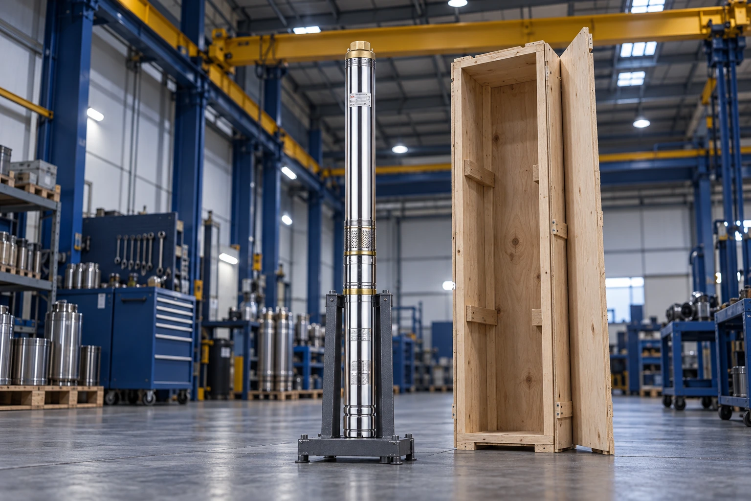
Check the handling route above the well as carefully as the route below it. The available height, shelter opening, lifting position and work area affect how the riser sections and pump assembly can be moved. A physically compact pump can still be difficult to service where a fixed roof or crowded equipment prevents safe handling.
Keep the proposed lift and support method with the equipment review. Do not use the electrical cable as a substitute for the specified support arrangement. Where a permanent sleeve, liner or fitting is proposed, ask how it changes removal of the pump. A service plan should describe which parts are removed together and which remain in the well.
Allow the contractor to assess future changes such as deposit accumulation or replacement accessories. The aim is not to predict an arbitrary amount of buildup. It is to avoid approving a fit that depends on a pristine opening, undocumented components or an improvised removal method. Photographs of staging equipment can support the discussion but cannot replace the actual access survey.
Send a complete diameter enquiry
Provide the well log, verified opening dimensions, intended setting depth, flow and head duty, supply conditions and known water-quality issues. Attach sketches or photographs showing wellhead access. Name the proposed pipe, valve and cable arrangement so the supplier reviews the same assembly the contractor expects to install.
Request a written response covering the maximum assembly envelope, required installation clearance, accessory compatibility and cooling instructions. Keep dimension units explicit and distinguish nominal connection size from measured outside diameter. Ask which drawing revision supports the answer, especially if the motor or accessories change during ordering.
Before release, compare the quotation, selected drawing and contractor’s fit review. Resolve discrepancies before dispatch. A complete enquiry reduces the risk of receiving a hydraulically suitable pump that cannot be installed or retrieved in the available well.
Further learning: pressure and flow are separate checks
Practical Engineering’s educational explanation below helps clarify why a pump’s physical size is not enough to establish hydraulic suitability. It provides conceptual context for the duty review; it does not specify borehole clearance or replace a selected pump curve.

Watch the Practical Engineering pressure and flow explanation.
Preguntas frecuentes
Can a nominal four-inch pump fit every four-inch well?
No. Compare the actual maximum assembly envelope with the usable inside opening and the required clearance. Nominal labels can describe different measurements, and accessories or casing condition can change the fit.
Should I measure only the widest part of the pump?
Measure or obtain drawings for the entire downhole assembly. The motor, cable protector, valve, pipe joint or cooling sleeve may be wider than the hydraulic section.
Is the borehole’s drilled diameter the same as available pump space?
No. Installed casing, liners and their condition determine the opening through which the equipment must pass. Use the finished well survey rather than the original drilling diameter.
Does choosing a smaller diameter reduce the required head?
No. The installation’s pumping water level, delivery elevation, required pressure and route losses establish the duty head. Physical fit and hydraulic duty must both be satisfied.
What should I do when well dimensions are uncertain?
Ask a qualified well contractor to verify the relevant passage and document its limitations. Keep the order conditional until the selected assembly’s fit and retrieval method are approved.