
Oil transfer pump low flow troubleshooting should begin by confirming the delivered flow and the conditions under which it fell. Record the liquid identity and temperature, tank levels, suction and discharge pressures, pump speed, valve positions and operating time. Compare those readings with an accepted baseline at the same duty. Low flow can result from a restricted or leaking inlet, air entry, higher viscosity, increased backpressure, reduced speed, wear or an incorrect measurement. Replacing the pump before separating these causes can leave the original problem in place.
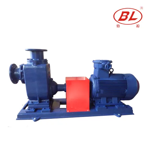
This guide concerns an industrial transfer package, particularly the centrifugal operating principle used in a CYZ-A self-priming oil pump. It does not provide a universal repair procedure for vehicle engine lubrication systems, small automotive extractors or positive-displacement pumps. Identify the actual mechanism first using the centrifugal versus gear pump comparison. Apply the manufacturer’s limits and the site’s approved isolation procedures throughout the investigation.
Establish whether the flow actually changed
Distinguish a lower flow reading from a longer batch-transfer time. A batch can take longer because the starting and finishing tank levels changed, the hose route was extended, or the operator included a waiting period. Check the measurement boundary, time interval and any recirculation or bypass path. A meter upstream of a bypass may report more flow than actually reaches the destination.
Verify the instrument’s suitability for the liquid and operating range. Meter calibration, installation conditions and the presence of air can affect the reading. If an independent measurement is permitted, compare safely measured transferred volume over a recorded interval with the meter total. Do not open a hazardous transfer system or improvise an open-container test. The aim is to validate the observation using an approved method, not create an additional exposure.
A useful fault record has a last-known-good condition, the first affected transfer and changes made between them. Note a new oil batch, colder weather, tank cleaning, hose replacement, motor work or a valve adjustment. These changes help prioritize checks, but they are leads rather than proof. Keep the original values instead of overwriting them when a setting changes.
Stop for leaks, unsafe conditions or loss of liquid
Before further operation, assess visible leakage, abnormal heat, severe noise, unusual vibration and evidence that the pump is no longer receiving liquid. Follow the site’s stop and escalation criteria. Self-priming capability is not permission to run dry, and a motor that continues to turn does not prove that the mechanical seal or pump internals are adequately wetted.
For flammable, harmful or unknown oil, the responsible site team must determine containment, ignition control, ventilation, protective equipment and waste handling. Electrical checks and disassembly require qualified personnel and the appropriate isolation process. Do not loosen fittings to search for suction or discharge pressure. Use the installed, approved measurement points and the equipment documentation.
Compare liquid temperature and viscosity
Obtain the liquid’s viscosity data at the measured transfer temperature. A different grade or colder oil can increase flow resistance, alter the pump’s performance and change power demand. Comparing a cold start with a warm afternoon transfer without accounting for viscosity can make a sound package appear defective. Conversely, attributing every winter problem to cold oil can conceal a blocked inlet.
Record bulk liquid temperature, ambient conditions and the point where temperature was measured. Check the actual product identity and any dilution, contamination or water content with the liquid supplier. Do not heat a tank, blend a thinner or change the oil merely to improve the pump reading without an approved process review. The Hydraulic Institute explanation of viscosity effects provides background for why water-based assumptions may not describe an oil duty.
Inspect the supply route before opening the pump
Review the source tank level, venting arrangement, inlet submergence and every accessible valve and hose on the suction route. A falling source level changes the available inlet conditions. A tank vent problem can also develop during transfer rather than at startup. Confirm venting through the responsible site procedure; do not remove a tank cap as an improvised remedy for an unknown liquid.
Check whether an approved strainer indication or pressure measurement suggests a restriction. A soft hose may collapse only during operation, while debris can move and intermittently cover an inlet. Air can enter a suction joint without leaving a visible external oil leak. Photograph the arrangement and record the condition before any permitted adjustment. The separate suction-pipe sizing and air-leak guide covers layout inputs; confirm the exact installed package rather than applying a generic pipe size.
Read inlet and outlet evidence together
Discharge pressure alone cannot identify the fault. Record inlet and outlet pressures at known locations, elevations and times along with flow and speed. A restricted delivery path can reduce centrifugal-pump flow while pressure near the pump rises; inadequate inlet supply can produce a different pattern. These are diagnostic leads, not universal signatures. Gauge error, recirculation and mixed operating changes can obscure the pattern.
| Observed change | Useful next evidence | Frontera de decisión |
|---|---|---|
| Flow falls as the source tank empties | Level, inlet pressure, venting and submergence record | Confirm supply conditions before blaming wear |
| Cold batches transfer more slowly | Actual oil grade, temperature and viscosity data | Review the corrected duty; do not improvise heating |
| Delivery pressure rises while flow falls | Destination level, valve positions and downstream restriction | Compare with the approved curve and system layout |
| Unstable flow follows hose maintenance | Joint condition, hose behavior and air-entry checks | Use approved isolated inspection methods |
| Duty changed after motor work | Verified rotation, speed, supply and operating records | Qualified personnel must check electrical causes |
| Performance remains low at matched conditions | Verified instruments, curve comparison and inspection history | Escalate to documented internal inspection |
The table organizes the investigation; it does not authorize continued operation or establish a safe pressure limit. The Department of Energy pump-systems resources support assessing pump and system requirements together.
Check speed, rotation and control changes safely
Confirm the actual operating speed and control mode against the accepted baseline. A changed speed command, drive limit, supply problem or control signal can shift the operating point. After motor maintenance, rotation must be verified using the manufacturer’s approved method. Do not infer correct rotation from motor noise, and do not instruct an unqualified operator to change wiring.
For a generator-fed package, compare readings during starting and stable running, including other connected loads. For an engine-driven package, use the engine and pump instructions to review governed speed and load response. These are different arrangements and should not be combined into a generic “increase speed” instruction. Any proposed speed change requires a review of the pump, motor, seal, piping and process limits.
Investigate wear only after matching the duty
When instruments, liquid, inlet conditions, system resistance and speed have been checked, compare the measured duty with the correct manufacturer performance information. Confirm the actual impeller and configuration. A curve for another diameter, speed or liquid condition is not a reliable wear test. Ask the supplier how to account for the documented oil properties and how to interpret the uncertainty of the field readings.
Internal inspection may find wear, blockage, damage or an assembly problem, but it should follow isolation and a documented service scope. Obtain the actual clearances, allowable wear limits and replacement procedure. Do not grind, machine or adjust an impeller using a generic online clearance. Preserve photographs and measurements so the failure can be related to contamination, alignment or operating history rather than treated as an unexplained replacement event.
Run a controlled comparison after correction
Record the proposed cause, the evidence supporting it and the authorized corrective action before making a change. Where operationally practical, change one variable at a time. After maintenance, follow the required fill, venting, guarding and return-to-service checks. Confirm that the system can operate safely before attempting the comparison.
Use the same measurement boundary and a comparable liquid temperature, source level, destination level and speed. Log flow, pressures, temperature and observations together. A higher flow reading at a lower required head does not by itself prove a repair succeeded. Acceptance should address the required duty and stable operation within the approved envelope, including leakage, vibration and relevant protection functions.
Give the supplier an actionable fault report
Include the pump identity and serial number, liquid information, original duty, last good record, current measured record, instrument locations, a simple layout and all recent changes. State whether the issue occurs at startup, after warming, near an empty tank or continuously. Identify temporary changes already attempted so the supplier can interpret the current arrangement correctly.
If the package was selected for a different liquid or transfer route, revisit the complete oil-transfer selection envelope before ordering a larger unit. Where seal leakage accompanies the flow problem, use the seal-failure review as a separate investigation. Reference-based illustrations here identify the relevant product family; they do not document an actual site test, sample analysis or approved hose connection.
Further learning: pressure and flow
Practical Engineering explains how pump behavior and system resistance interact in the educational video below. It helps interpret why a pressure change and a flow change must be considered together. Its demonstrations do not set limits for this oil-transfer package.

Watch the Practical Engineering explanation.
Preguntas frecuentes
Does low oil-transfer flow always mean the pump is worn?
No. Verify measurement, liquid properties, inlet supply, downstream resistance and actual speed before concluding that internal wear is responsible.
Why is flow lower with colder oil?
Higher viscosity can increase system losses and change pump performance. Confirm the actual liquid and its viscosity at the measured temperature, then review the duty with the supplier.
Can a suction air leak occur without an external oil leak?
Yes. A joint operating below atmospheric pressure can admit air without showing an outward oil leak. Use the approved inspection and testing method for the installed system.
Should I increase motor speed to restore flow?
Only after the responsible engineers approve the changed duty and all equipment limits. Raising speed without identifying the cause can worsen inlet, power, seal or pressure problems.
What proves a low-flow correction worked?
A controlled comparison at matched duty conditions should demonstrate the required flow and head, stable operation and acceptable equipment condition under the approved acceptance criteria.