
Pump casing dowel pin inspection checks the identity, condition, location and fit of the pins used to locate mating pump components. Record the as-found arrangement before separation, protect the matching holes and compare measurements with the supplied drawing. A locating pin is not a substitute for correct flange condition, register fit or bolt loading, and casing bolts should not be used to force misaligned dowels into place.
This guide supports controlled overhaul work on assemblies that actually use dowels. Not every pump casing has the same locating system. The focus is pin-and-hole condition and traceability, separate from casing-register measurements and shaft alignment. Confirm the construction before applying any removal or installation method.
Identify the locating system on the drawing
Obtain the pump serial number, assembly drawing and dismantling procedure. Locate each dowel and identify whether it is cylindrical, tapered, threaded for extraction or part of another locating arrangement. These details determine how it should be handled. A method appropriate for one type may damage another.
Record which component retains the pin during normal separation and whether matched locations are identified. Do not assume that all pins of similar diameter are interchangeable. The location, material, length and fit can be important even when two pins look alike on a bench.
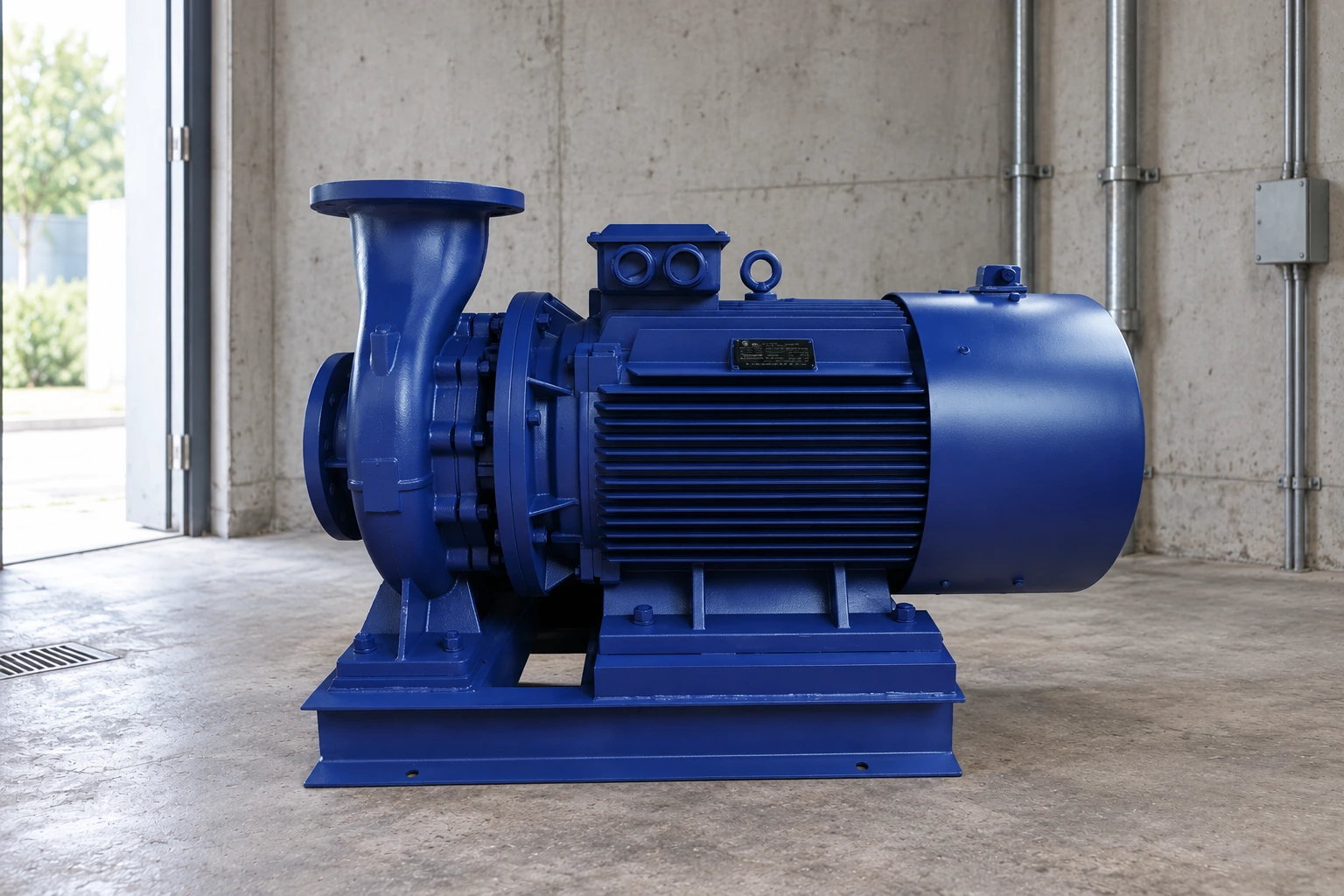
El Bombas horizontales en línea ISW is a relevant centrifugal-pump product reference. Its image does not prove the presence or dimensions of a particular dowel. Use the supplied variant’s drawing before claiming any internal arrangement or ordering a locating component.
Preserve the as-found relationship
Photograph the assembled joint and mark orientation using an approved method that does not damage a sealing or locating surface. Record existing identification marks, missing pins, protrusion and any evidence of previous repair. A fresh punch mark in a precision face can create a new problem, so choose the marking location deliberately.
Document whether the joint separated normally or resisted at a particular location. Keep that observation separate from the diagnosis. Binding may involve corrosion, loading, gasket adhesion, a damaged dowel or another feature. It is not proof that every tight joint needs enlarged holes.
El OISD rotary-equipment inspection reference provides broader component-inspection context. The EPRI maintenance report also identifies housing-to-casing dowel presence, fit and final alignment as inspection concerns. It supports the inspection scope without supplying Borra-specific dimensions or repair limits.
Separate the casing under a controlled procedure
Confirm isolation, depressurization, draining and the lifting arrangement before dismantling. Account for component weight and the possibility of residual liquid. Dowels are locating features, not lifting attachments. Do not attach lifting equipment to a pin merely because it appears convenient.
Use the specified separation or jacking features. Apply force only where the procedure permits it and maintain control of the component as the joint releases. Hammering or levering against an unidentified precision face can damage the casing before inspection begins.
If the assembly binds, stop and determine the cause. Check that all retaining hardware is removed and the lifting direction matches the intended separation. A pin may need a specific extraction method, but forcing the whole casting around it is not a substitute for identifying that method.
Inspect pins before cleaning removes evidence
Record corrosion, fretting marks, scoring, flattened areas, impact damage and abnormal contact patterns. Inspect any extraction thread or fastening feature. A damaged extraction feature can complicate later work even when the pin’s locating surface appears acceptable.
Clean according to the material and inspection procedure, then examine the surface under suitable lighting. If a crack or other significant defect is suspected, obtain the specified additional examination. Visual inspection alone should not be reported as proof that no subsurface defect exists.
Do not polish a damaged pin until it fits more easily and then describe it as restored. Material removal changes the locating fit. Any rework needs an approved method, final dimensional requirements and inspection record. Otherwise, use a confirmed replacement or seek engineering direction.
Measure the matching holes as well as the pins
Measure at defined positions using suitable calibrated instruments. Record the pin diameter or taper features and the corresponding hole geometry required by the drawing. Note ovality, bell-mouthing, corrosion pits and asymmetric wear where observed. A single diameter reading may miss the feature that causes poor location.
Protect the hole entrance and internal surface during cleaning. Removing burrs may be an approved task, but changing the bore or taper is a repair decision. Do not use a drill or reamer simply to make assembly easier without a defined final geometry.
Confirm which fit applies to each side of the joint. One side may retain the pin differently from the mating side. A statement that the pin should be tight everywhere is not a universal rule. The intended assembly and removal behavior belongs to the drawing and manufacturer instructions.
Use a traceable inspection table
| Característica | Registro de inspección | Release basis |
|---|---|---|
| Pin identity | Drawing item, type, material and location | Confirmed assembly applicability |
| Locating surface | Damage and measured geometry | Specified fit and condition criteria |
| Extraction feature | Thread or removal detail condition | Approved removal and reuse procedure |
| Retaining hole | Dimensions and surface condition | Required retention arrangement |
| Mating hole | Fit, wear pattern and alignment concern | Supplied drawing and inspection criteria |
| Joint faces and registers | Separate damage and dimensional records | Their own acceptance requirements |
| Reparación previa | Oversize parts, sleeves or altered holes | Approved repair documentation |
The table is a record structure rather than a dimensional specification. Do not invent a fit class, interference or clearance from the pin’s nominal diameter. A correct numerical limit must come from the applicable design or an approved repair instruction.
Distinguish dowels, registers and casing bolts
Dowels and registers can both contribute to location, but they are different geometric features. A sound dowel does not prove that a register diameter is correct, and a sound register does not excuse a damaged pin. Keep the casing-register inspection record separate.
Casing bolts provide the designed clamping action. They should not become assembly presses for pulling a cocked joint over a damaged locating feature. If a joint will not seat using the prescribed method, identify the interference before applying further load.
Review bolt condition and the gasket arrangement independently. The casing-bolt inspection guide y casing-gasket replacement guide address those tasks. A joint can have acceptable dowels and still be unsuitable for final assembly because another interface is damaged.
Control repair and replacement decisions
If wear or damage exceeds the defined criteria, request a repair proposal that identifies the final locating geometry and the relationship between mating components. Replacing only the pin may not restore a worn hole. Conversely, an enlarged replacement pin can require coordinated work on both sides of the joint.
Document previous oversize repairs or inserts. A standard spare may no longer match an altered casing. Obtain the repair history and measure the actual assembly rather than assuming that the original catalogue part restores the present configuration.
Avoid welding, peening or adhesive retention as an undocumented workshop shortcut. Such methods can change material condition, geometry and future dismantling behavior. If an engineered repair uses a particular process, preserve the procedure, inspection results and approval with the machine record.
Reassemble without concealing interference
Clean and protect the mating features according to the supplied procedure. Confirm correct pin identity, location and installation orientation. Use only the specified lubricant or preparation where required. A coating chosen merely to make the joint slide together can affect fit or contaminate another interface.
Lower or position the mating component in a controlled manner and observe the intended engagement. Keep hands out of pinch points and use approved alignment tools. Do not use fingers to guide a suspended casing over a pin.
If the joint stops unexpectedly, lift or separate it safely and inspect for interference. Check pin projection, hole condition, orientation, foreign material and the gasket arrangement. Tightening the bolts until the gap disappears can conceal damage rather than prove correct seating.
Verify the assembled machine as a whole
After assembly, perform the specified checks for joint seating, fasteners, clearances and free rotation where applicable. Casing location is one contributor to the final geometry. A satisfactory pin inspection does not replace shaft, rotor, bearing or coupling checks required by the overhaul plan.
Record any abnormal rotation resistance or contact before startup. Investigate through the approved procedure rather than expecting running to wear the interference away. The final release should identify which component inspections and assembly checks supported the decision.
Retain the photographs, measurement sheet, replacement part numbers and repair approvals. For future work, clearly identify any matched locations or nonstandard repair dimensions. Good traceability reduces the chance that the next overhaul mixes pins or unknowingly reverses a previous engineered repair.
Prepare a supplier inquiry with enough detail
Send the serial number, assembly drawing item, pin type, actual measurements, matching-hole condition and photographs of the location. State whether the request is for a standard spare, an oversize repair or help identifying an unknown previous modification.
Ask the supplier to confirm the intended fit and installation method for the actual assembly. Do not order solely by measured pin diameter or a photograph taken after removal. Those details may identify approximate size while missing taper, retention, material or location-specific requirements.
Aprendizaje adicional: ajustes y tolerancias
The NPTEL lecture below explains the dimensional language used when comparing mating components. It supports understanding a drawing but does not establish a dowel fit, allowable wear or approved repair size for this pump.

Preguntas frecuentes
¿Todas las carcasas de las bombas utilizan pasadores de posicionamiento?
No. Locating arrangements vary with design and model. Confirm the supplied drawing. A general product photograph or a manual for another pump cannot establish the pin arrangement on the machine being overhauled.
Can I pull the casing together with its bolts?
Do not use bolts to overcome unexplained locating interference. Follow the prescribed assembly method and investigate a joint that will not seat. Forcing it together can damage pins, holes, faces or other internal relationships.
Is replacing the dowel enough to repair a loose fit?
Not necessarily. Inspect the matching holes and the complete locating geometry. A new pin cannot automatically restore a worn or distorted bore. Use an approved repair decision with defined final measurements.
Can I polish a scored pin for reuse?
Only if an approved repair method permits the work and defines the final geometry and acceptance criteria. Uncontrolled polishing changes the fit. Record damage before cleaning and obtain the correct replacement when reuse cannot be justified.
What records are most useful for the next overhaul?
Keep pin locations, orientation photographs, actual measurements, drawing revisions, replacement numbers and any oversize repair details. Record the final assembly checks so the next technician can distinguish original features from approved modifications.