
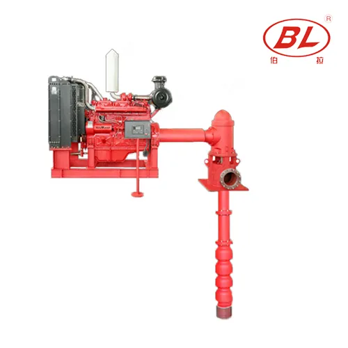
A vertical turbine fire pump is typically considered when the fire-water source is below the pump-room elevation or when suction conditions favor a wet-pit vertical arrangement. Selection requires the fire-system rated flow and pressure, water-source levels, intake geometry, required submergence, bowl setting, column length, discharge-head elevation, driver, available power or diesel arrangement, seismic and structural loads, materials, listed or approved configuration, and the governing fire code. The pump, driver, controller, fuel or power supply, relief and test arrangements, and water source form one system. NFPA 20 or another applicable standard must be applied by the responsible fire-protection engineer and authority having jurisdiction; a product curve alone is not an approval.
This guide is an early-stage engineering and procurement framework. Confirm every calculated value, operating limit, safety requirement, and regulatory obligation against current project documents, approved manufacturer data, and the responsible engineer’s review before selecting equipment or changing an installed system.
When the vertical turbine arrangement fits
Unlike a horizontal pump that needs an acceptable suction supply at its inlet, a vertical turbine unit places the bowl assembly below the water surface and transmits power through the column to the pump. This can suit open reservoirs, tanks, wet pits, or wells where the minimum water level is below the pump-room floor. The arrangement does not remove intake-design obligations. Low water level, vortex formation, sediment, poor approach flow, or inadequate submergence can impair performance. Confirm that the proposed water source and structure can support rated demand for the required duration under the governing design. Compare alternatives only after the source level, access, structural work, and maintenance method are understood.
Define rated and maximum-demand conditions
The fire-protection engineer determines the required rated flow and pressure from the hydraulic design and applicable rules. The pump selection must also be reviewed at other required points on its curve, including churn and higher-flow conditions where applicable. Record elevation differences from the minimum water level through the discharge reference and include friction in column, fittings, valves, test piping, and discharge network. A fire pump is not selected like an ordinary process pump that continuously follows a best-efficiency operating point. Its acceptance criteria, driver sizing, controller, and testing follow the applicable fire-protection framework. Use the current adopted standard, project specification, listing information, and authority requirements.
Design the intake and bowl setting
Obtain maximum, normal, and minimum water levels, pit or tank dimensions, approach geometry, sediment allowance, and water quality. The pump manufacturer should state bowl diameter, minimum submergence, spacing, allowable intake conditions, and any anti-vortex or flow-straightening requirements. Set the bowls deep enough for the minimum credible level without placing the intake where sediment or debris is concentrated. Structural design must accommodate the discharge head, column, driver, torque, hydraulic thrust, seismic forces, and maintenance lifting. The suction source should be inspectable and protected against blockage. Hydraulic modeling or a physical model may be warranted for complex multi-pump intakes; generic sketches are not sufficient evidence.
Project decision table
| Review item | Required evidence | Risk if omitted |
|---|---|---|
| Minimum water level | Survey/source study and design basis | Loss of submergence |
| Rated flow and pressure | Fire-system hydraulic calculation | Incorrect pump duty |
| Intake geometry | Coordinated civil and pump drawings | Vortexing or poor approach flow |
| Bowl setting and column | Manufacturer arrangement and loads | Sediment intake or mechanical issues |
| Driver/controller | Approved matched package data | Insufficient starting or power |
| Test and removal route | Commissioning and lifting plan | Unverifiable or unmaintainable system |
Coordinate column, driver, and discharge head
Column diameter and length affect friction, shaft dynamics, alignment, and installation. Review line-shaft bearings or submersible-motor construction as applicable, lubrication method, shaft and coupling details, column joints, and materials. The driver must cover pump demand across the required curve and satisfy the applicable fire-pump rules. For diesel arrangements, coordinate engine rating, cooling, fuel, exhaust, ventilation, starting batteries, controller, and room conditions. For electric drivers, coordinate service reliability, voltage, starting, feeder, controller, and emergency power rules. The discharge head, base, piping loads, and flexible or seismic provisions must be shown on coordinated drawings rather than split among suppliers.
Plan testing and maintainability

Provide a safe method to test required flow without damaging the site or depleting the source unexpectedly. Show test header or flow-meter arrangement, drainage, recirculation restrictions, and instrumentation. Maintenance planning must include removal of driver, head, column, and bowls; lifting height and crane capacity; storage space; isolation; water-source access; and inspection of submerged parts. A compact pump room can become unserviceable if the longest component cannot be removed. Establish inspection, testing, and maintenance responsibilities under the current applicable standard. Preserve baseline vibration, pressure, speed, current or engine readings, water level, and test flow for comparison.
Build a reviewable procurement package
The package should include hydraulic calculations, rated point and required curve conditions, source-level data, intake drawings, submergence and bowl setting, column length, materials, driver, controller, power or fuel scope, structural and seismic criteria, environment, listings or approvals required, test arrangement, documentation, spares, destination, and authority comments. Request certified curves, general arrangement, weights and loads, bowl and column details, driver data, controller data, minimum submergence, installation instructions, and test certificates within the project's approval framework. Hold design, factory, installation, and acceptance reviews with responsibilities clearly assigned. Do not substitute an unverified pump because flange size or nominal flow appears similar.
How to compare supplier offers
The final technical review should trace every requirement to evidence. Map rated flow and pressure to the certified curve; minimum water level to bowl setting and submergence; intake geometry to the manufacturer's criteria; column length to shaft, bearing, and structural details; and driver demand to the accepted curve conditions. Confirm that required listing or approval applies to the exact pump, driver, and controller configuration being offered. Review the division of supply for discharge head, base, column, bowls, shafting, driver, controller, batteries or electrical feeder, cooling, fuel, exhaust, valves, test equipment, and commissioning. Resolve conflicts between civil drawings, pump drawings, and fire-protection plans before release. Factory testing cannot prove site intake performance, while site testing cannot compensate for an unapproved component substitution. Both reviews need documented acceptance criteria and responsibility. The submittal should also identify the current standard editions, authority comments, deviation list, coating and corrosion assumptions, shipment split, field assembly procedure, alignment checks, lubrication requirements, and the instruments needed for acceptance. Any proposed substitution should reopen the affected hydraulic, structural, electrical, listing, and maintenance checks rather than being approved from a short equivalency statement.
How this guide connects to BORRAPUMP equipment
This article supports early project review for the vertical turbine fire pump product line. It does not assign a final model. Send the duty conditions, liquid data, power supply, installation drawings, controls, quantity, and destination so the product configuration can be checked against the actual project.
Related BORRAPUMP engineering guides
Authoritative sources and further learning
NFPA 20 standard page NFPA 25 standard page OSHA Fire Safety. These sources establish general engineering, safety, or regulatory context; the current adopted rules, equipment manuals, and project approvals remain controlling.
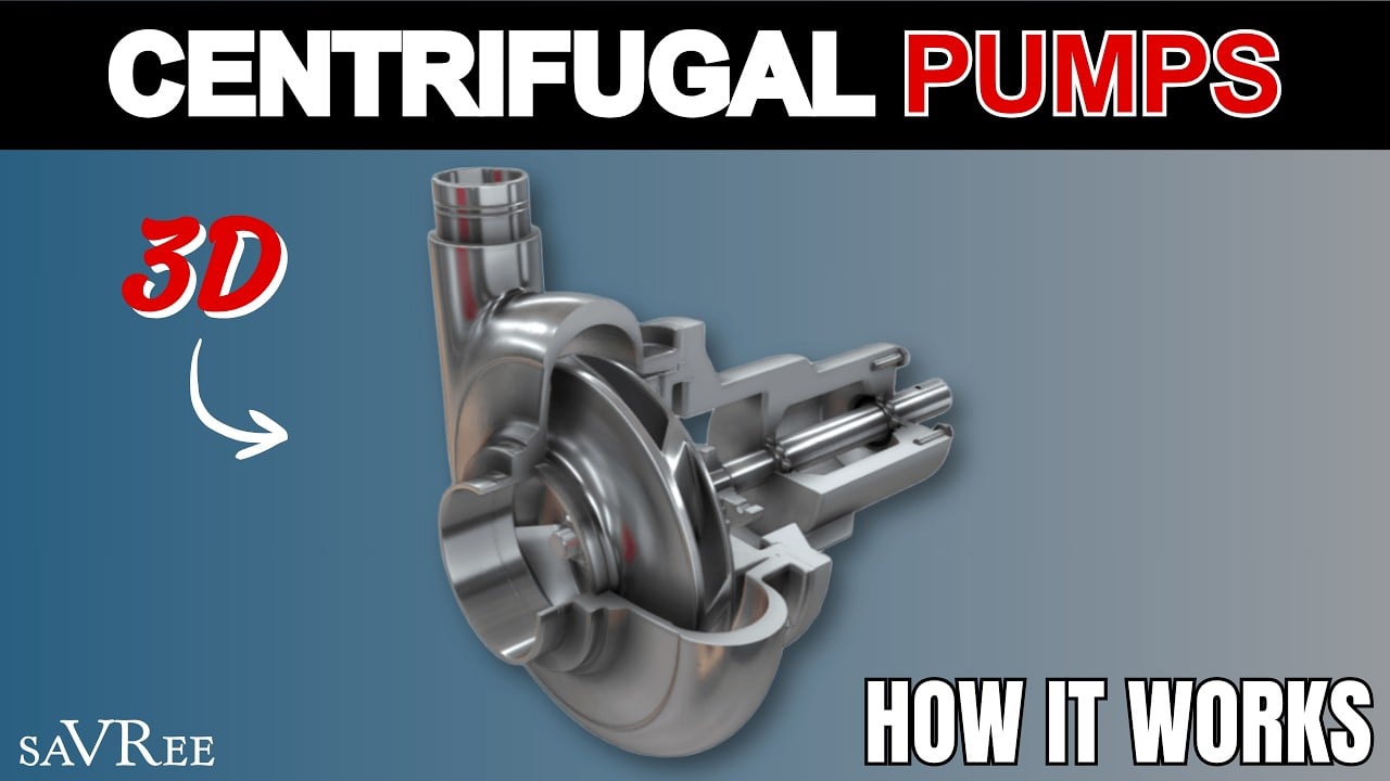
Educational video by saVRee: How Centrifugal Pumps Work. It explains background principles and does not replace project-specific instructions.
Frequently asked questions
Why use a vertical turbine fire pump?
It can suit a source below pump-room elevation by placing the bowl assembly below the water surface.
Is pump rated flow enough for selection?
No. Review required curve conditions, water levels, intake, driver, controller, tests, and applicable approvals.
How is bowl setting chosen?
Use minimum water level, required submergence, intake geometry, sediment allowance, column design, and manufacturer limits.
Who approves the final arrangement?
The responsible fire-protection engineer and authority having jurisdiction apply the adopted codes and project requirements.
Final procurement checkpoint
Before order placement, reconcile the approved duty and drawings with the supplier curve, motor or driver, materials, dimensions, weights, connections, controls, accessories, tests, documentation, spare parts, delivery boundary, and destination requirements. Record every assumption that remains open. Installation, electrical work, hazardous-liquid handling, fire-protection work, excavation activity, and energized testing must be performed by qualified personnel under approved procedures and applicable rules.