
Reading a diesel fire pump diagram starts at the water source and suction arrangement, then walks the fire-flow path, pressure-maintenance branch, diesel fuel interfaces, and controller notes — without treating a supplier sketch as approval or a wiring instruction. Project teams use that order to catch missing fuel or sensing notes before procurement locks scope. This rebuild strengthens the live checklist for United States B2B buyers reviewing diesel fire layouts.
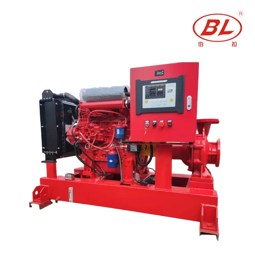
Part 1. Why Source and Suction Come Before the Engine Photo
A diesel fire pump diagram that opens with a product photograph and never names the water source is incomplete for project review. Locate the documented tank, pit, or suction supply, the strainer or foot arrangement if used, and any elevation notes that affect available suction. Only after that path is clear should the team focus on the diesel driver package.
| Diagram focus | Review question | Risk if skipped |
|---|---|---|
| Water source | Flooded suction, tank-fed, or other documented arrangement? | Wrong package geometry assumptions |
| Suction path | Continuous route with isolation and access? | Air or restriction surprises later |
| Main diesel pump tag | Matches equipment schedule? | Family brochure treated as model |
| Discharge header | Continues to the fire system as designed? | Incomplete hydraulic story |
Searchers looking for a diesel fire pump diagram usually need a walk-order for documents, not a decorative cutaway. Continue afterward with the BORRAPUMP Fire Pump guide and the sibling fire pump system diagram when the whole system context is required.
Part 2. How Fire-Flow Differs From Pressure Maintenance on the Sketch
The main diesel fire pump path delivers fire-flow duty. A jockey or pressure-maintenance branch holds system pressure against small losses. Mixing those duties on a sketch creates wrong testing expectations and wrong RFQ language.
| Path on the diagram | Role | Review trap |
|---|---|---|
| Main diesel fire pump | Fire-flow delivery per design | Treating it as a building booster |
| Pressure-maintenance / jockey | Small makeup against leakage | Assuming it replaces fire-flow |
| Sensing reference | Pressure signal for maintenance control | Undocumented field tees |
| Test / drain notes | Procedure support | Silent drawing equals unusable for tests |
Keep electric-versus-diesel differences in mind when comparing sketches: diesel layouts add fuel and starting interfaces that electric fire diagrams do not carry. For electric layouts, use the related electric fire pump diagram after this diesel walk is complete.
Part 3. Which Diesel Fuel and Support Interfaces Belong on the Drawing
Fuel-system gaps are common delivery surprises. Mark supply and return concepts, fill, vent, drain, level indication, containment notes, and whether the tank is package-mounted or field-supplied. Those items should match the current drawing revision — not a catalog default.
| Fuel / support item | Document question | Escalate when |
|---|---|---|
| Tank supply split | Package-supplied or site-supplied? | Quotation silent |
| Fill / vent / drain | Identifiable on current revision? | Missing symbols |
| Level indication | Required devices named? | Assumed from photo |
| Containment / protection | Notes present for the project? | Undefined field scope |
| Starting / batteries | Documented with the driver package? | Scope left to assumption |
Detailed tank-scope questions belong with diesel fire pump fuel tank scope once the diagram walk flags a gap.
Important: Never copy diesel fire pump controller setpoints, fuel capacities, or test distances from a generic diagram. Use the approved project documents and the installed equipment manuals. (Source: Hydraulic Institute / project design documents.)
Part 4. Where Controller, Sensing, and Alarm Paths Appear
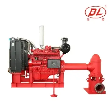
Find the controller, sensing connection, and remote annunciation notes. Exact sequences and pressure bands belong to the approved design and the controller documentation for the installed unit — not to a blog interpretation.
| Interface | Evidence to file | Escalate when |
|---|---|---|
| Controller model notes | Submittal / schedule match | Mismatch or missing |
| Sensing line | Connection point identified | Undocumented field tee |
| Remote alarms | Point list with names | Lamp-color assumptions |
| Power / starting notes | Documented with diesel package | Silent electrical boundary |
Recurring field inspection evidence after handover is covered in diesel fire pump inspections, which is a different job from this diagram walk.
Part 5. What Valve, Test, and Drain Notes Make the Diagram Usable
A usable diesel fire pump diagram shows isolation, test outlets, drains, and gauges needed for the project procedure. Missing test-path notes should be logged as open items against the current revision rather than filled in from memory of another site.
| Usability check | Pass signal | Fail signal |
|---|---|---|
| Isolation | Pumps can be isolated for service | No valves shown where design needs them |
| Test outlet path | Identifiable for project procedure | No route or drain notes |
| Gauges / instruments | Locations support verification | Instruments only on brochure photos |
| Drain terminations | Where water goes is stated | Undefined flooding risk |
Do not invent hose lengths, orifice sizes, or pressure bands to make a silent drawing look complete.
Part 6. How Package Scope and Field Work Should Be Split for RFQ
List pumps, diesel driver, controller, valves, instruments, and documents in package scope. List field piping, fuel piping, electrical terminations, and civil work separately. A quotation that names exclusions is more useful than one that stays quiet.

| Project signal | BORRAPUMP route | Send with quote |
|---|---|---|
| Documented diesel fire package discussion | EDJ Integrated Fire Pump Set | Required flow and pressure with sources, water source, diesel driver needs, controller scope, fuel-tank split, destination, documents |
| End-suction diesel fire discussion | XBC-W family discussion after duty is clear | Duty point, suction arrangement, documents |
| Automatic diesel set discussion | Automatic diesel fire water pump discussion after schedule match | Tags, interfaces, document list |
Why not recommend landscape boosters or ordinary transfer pumps here: those machines address different duties and document sets; they are not substitutes for diesel fire-pump packages.
After the diagram questions are listed, contact BORRAPUMP with tagged drawing questions and the duty sheet.
Part 7. What Boundaries Apply to Diagram Review
Fits:
- Document review of diesel fire layouts for contractors and buyers preparing RFQs.
- Separating fire-flow, pressure maintenance, fuel, and controller notes on a sketch.
Does not fit:
- Claiming listing, authority acceptance, or code compliance from this article.
- Using the sketch as a wiring, fuel-fill, or setpoint instruction.
- Inventing numeric capacities, distances, or pressure bands.
Must be confirmed before quote:
- Required flow and pressure with sources, water source description, diesel driver requirements, controller and signal expectations, fuel-tank supply split, connection list, destination, and required documents.
This article does not certify equipment for any jurisdiction. Final acceptance requires project documents, responsible professionals, and verified equipment evidence.
FAQ
What should I look for first on a diesel fire pump diagram?
Start with the water source and suction path, then locate the main diesel pump, pressure-maintenance branch, fuel interfaces, and controller notes.
Is a supplier layout the same as the engineer drawing?
No. Supplier layouts explain package scope; the approved project drawing defines the accepted system.
Where does the fuel tank appear on the diagram?
Wherever the project documents place it. Confirm whether it is package-mounted or field-supplied before ordering.
Can setpoints be read from a generic diesel fire pump diagram?
No. Setpoints and sequences come from the approved design and verified controller documentation for the installed equipment.
How is the jockey pump shown relative to the diesel fire pump?
As a separate pressure-maintenance path. It should not be confused with fire-flow duty.
What belongs in a diesel fire pump package RFQ?
Flow and pressure with sources, water source, diesel driver requirements, controller scope, fuel-tank split, connections, documents, and destination.
Does this diagram guide certify the system?
No. Certification and acceptance require responsible professionals, authorities having jurisdiction where applicable, and verified project evidence — not a blog checklist.
Which sibling articles help after diagram review?
Use the fire pump system diagram, diesel fuel-tank scope, and diesel inspection checklist articles for related review angles after this walk-order is complete.