
Size and locate a fire pump test header so the required pump test flow can be discharged and measured safely with acceptable pressure at the outlets. Start with the applicable test flow, available pump pressure, hose and nozzle arrangement, friction from the pump discharge to the header, outlet count and size, personnel access, drainage, and the approved destination for water. A convenient wall location is not enough if the route cannot pass full test flow or creates an unsafe discharge area.
Sécurité et périmètre : Les pompes à incendie et leurs entraînements sont des équipements de sécurité des personnes. Les travaux relatifs à l'hydraulique, à l'électricité, au diesel, au carburant, aux batteries, à la pression, aux équipements rotatifs, aux essais et aux pannes doivent respecter la conception approuvée actuelle, les instructions du fabricant, les normes applicables et l'autorité compétente. Ce guide explique le processus de décision en matière d'ingénierie ; il n'autorise pas les modifications sur le terrain, les contournements ou l'exploitation par du personnel non qualifié.
Define required test flow
Use the accepted testing requirement and pump curve, including any higher-flow verification. Do not size the header only for routine churn tests. Treat this as a system condition rather than an isolated component choice. Identify the source of every input, the unit used, the operating condition it represents, and the person responsible for approval. If information is preliminary, mark the assumption and test how the decision changes at a conservative boundary. This prevents a neat calculation from hiding an uncertain water level, pressure, valve position, driver condition, or simultaneous demand.
For fire pump test header sizing, verify this section against the selected pump curve, the actual site arrangement, manufacturer instructions, and the current requirements accepted by the authority having jurisdiction. Check the installed condition as well as the drawing because pipe routes, elevations, supports, controls, and access often change during construction. Record the result in a form that can be repeated during commissioning and later inspection. Do not change a safety-critical setting or isolate fire protection without the approved impairment and restoration process.
Calculate pressure at the header
Start with pump discharge pressure at test flow and subtract elevation and friction through valves, pipe, fittings, and the header assembly. The most useful evidence is measured or approved project data, not a copied rule of thumb. Identify the source of every input, the unit used, the operating condition it represents, and the person responsible for approval. If information is preliminary, mark the assumption and test how the decision changes at a conservative boundary. This prevents a neat calculation from hiding an uncertain water level, pressure, valve position, driver condition, or simultaneous demand.
For fire pump test header sizing, verify this section against the selected pump curve, the actual site arrangement, manufacturer instructions, and the current requirements accepted by the authority having jurisdiction. Check the installed condition as well as the drawing because pipe routes, elevations, supports, controls, and access often change during construction. Record the result in a form that can be repeated during commissioning and later inspection. Do not change a safety-critical setting or isolate fire protection without the approved impairment and restoration process.
Select outlets and nozzles as a system
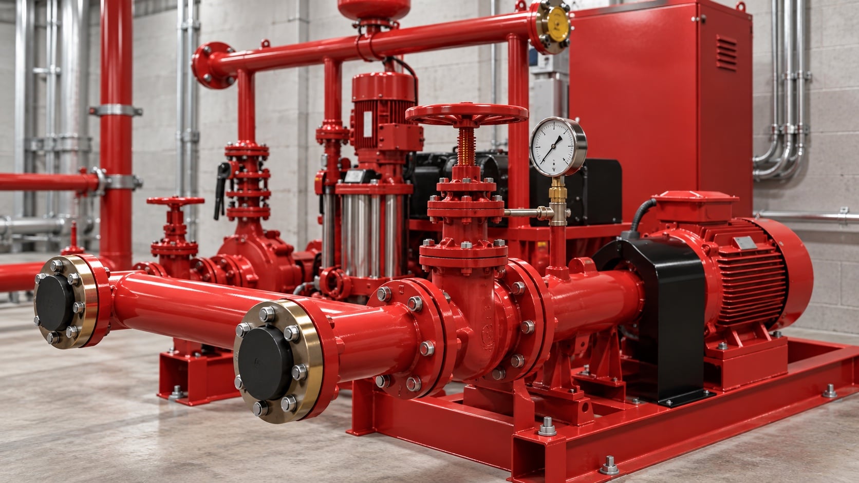
Outlet count, hose, playpipe or nozzle, and measurement method work together. Use approved equipment and calibration data. Review this condition at normal, test, and credible abnormal states before procurement. Identify the source of every input, the unit used, the operating condition it represents, and the person responsible for approval. If information is preliminary, mark the assumption and test how the decision changes at a conservative boundary. This prevents a neat calculation from hiding an uncertain water level, pressure, valve position, driver condition, or simultaneous demand.
For fire pump test header sizing, verify this section against the selected pump curve, the actual site arrangement, manufacturer instructions, and the current requirements accepted by the authority having jurisdiction. Check the installed condition as well as the drawing because pipe routes, elevations, supports, controls, and access often change during construction. Record the result in a form that can be repeated during commissioning and later inspection. Do not change a safety-critical setting or isolate fire protection without the approved impairment and restoration process.
Choose a safe location
Keep discharge away from entrances, traffic, electrical equipment, erosion, freezing hazards, and areas where high-force hoses cannot be restrained. The design team should turn this point into a traceable calculation or drawing note. Identify the source of every input, the unit used, the operating condition it represents, and the person responsible for approval. If information is preliminary, mark the assumption and test how the decision changes at a conservative boundary. This prevents a neat calculation from hiding an uncertain water level, pressure, valve position, driver condition, or simultaneous demand.
For fire pump test header sizing, verify this section against the selected pump curve, the actual site arrangement, manufacturer instructions, and the current requirements accepted by the authority having jurisdiction. Check the installed condition as well as the drawing because pipe routes, elevations, supports, controls, and access often change during construction. Record the result in a form that can be repeated during commissioning and later inspection. Do not change a safety-critical setting or isolate fire protection without the approved impairment and restoration process.
Table de décision pratique
| Header input | Design question | Vérification |
|---|---|---|
| Required test flow | What maximum flow must be demonstrated? | Accepted test procedure |
| Pump pressure | What pressure reaches the header? | Pump curve and loss calculation |
| Outlets and hose | Can the arrangement pass and measure flow? | Approved equipment data |
| Emplacement | Can water and hose reaction be controlled? | Site safety review |
| Drainage | Where does test water go? | Approved discharge plan |
| Supports | Can the assembly resist operating forces? | Structural and field inspection |
Provide valve and backflow arrangement
Follow the approved piping sequence from the pump discharge and maintain valve accessibility, indication, drainage, and protection against unintended flow. Treat this as a system condition rather than an isolated component choice. Identify the source of every input, the unit used, the operating condition it represents, and the person responsible for approval. If information is preliminary, mark the assumption and test how the decision changes at a conservative boundary. This prevents a neat calculation from hiding an uncertain water level, pressure, valve position, driver condition, or simultaneous demand.
For fire pump test header sizing, verify this section against the selected pump curve, the actual site arrangement, manufacturer instructions, and the current requirements accepted by the authority having jurisdiction. Check the installed condition as well as the drawing because pipe routes, elevations, supports, controls, and access often change during construction. Record the result in a form that can be repeated during commissioning and later inspection. Do not change a safety-critical setting or isolate fire protection without the approved impairment and restoration process.
Manage test water
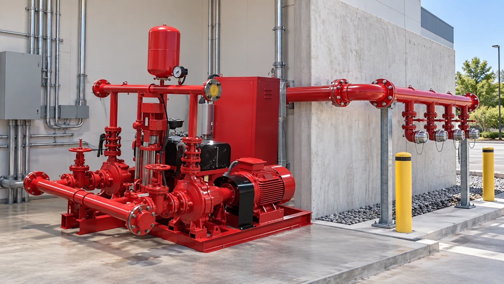
Plan discharge to a safe outdoor area, tank return, or other approved route. Confirm flooding, erosion, water-quality, and environmental constraints. The most useful evidence is measured or approved project data, not a copied rule of thumb. Identify the source of every input, the unit used, the operating condition it represents, and the person responsible for approval. If information is preliminary, mark the assumption and test how the decision changes at a conservative boundary. This prevents a neat calculation from hiding an uncertain water level, pressure, valve position, driver condition, or simultaneous demand.
For fire pump test header sizing, verify this section against the selected pump curve, the actual site arrangement, manufacturer instructions, and the current requirements accepted by the authority having jurisdiction. Check the installed condition as well as the drawing because pipe routes, elevations, supports, controls, and access often change during construction. Record the result in a form that can be repeated during commissioning and later inspection. Do not change a safety-critical setting or isolate fire protection without the approved impairment and restoration process.
Support and label the assembly
Provide structural support for pipe and hose forces, weather protection, caps, drainage, and durable identification without obstructing operation. Review this condition at normal, test, and credible abnormal states before procurement. Identify the source of every input, the unit used, the operating condition it represents, and the person responsible for approval. If information is preliminary, mark the assumption and test how the decision changes at a conservative boundary. This prevents a neat calculation from hiding an uncertain water level, pressure, valve position, driver condition, or simultaneous demand.
For fire pump test header sizing, verify this section against the selected pump curve, the actual site arrangement, manufacturer instructions, and the current requirements accepted by the authority having jurisdiction. Check the installed condition as well as the drawing because pipe routes, elevations, supports, controls, and access often change during construction. Record the result in a form that can be repeated during commissioning and later inspection. Do not change a safety-critical setting or isolate fire protection without the approved impairment and restoration process.
Witness the complete test
Use calibrated pressure and flow measurement, record pump speed and suction pressure, inspect the discharge area, and restore all valves after testing. The design team should turn this point into a traceable calculation or drawing note. Identify the source of every input, the unit used, the operating condition it represents, and the person responsible for approval. If information is preliminary, mark the assumption and test how the decision changes at a conservative boundary. This prevents a neat calculation from hiding an uncertain water level, pressure, valve position, driver condition, or simultaneous demand.
For fire pump test header sizing, verify this section against the selected pump curve, the actual site arrangement, manufacturer instructions, and the current requirements accepted by the authority having jurisdiction. Check the installed condition as well as the drawing because pipe routes, elevations, supports, controls, and access often change during construction. Record the result in a form that can be repeated during commissioning and later inspection. Do not change a safety-critical setting or isolate fire protection without the approved impairment and restoration process.
Comment cela se rapporte à l'équipement BORRAPUMP
BORRAPUMP fournit des équipements de pompage conçus pour des projets liés à l'eau et à la protection contre l'incendie. Examinez le document pertinent Configuration du produit BORRAPUMP à titre de point de départ, puis soumettez le débit, la charge, la source d'eau, l'entraînement, la puissance, les commandes, les conditions du site, les exigences applicables, la quantité et la destination requis. La sélection finale doit utiliser la base hydraulique du projet et la soumission approuvée ; ce guide ne prétend pas qu'une disposition de catalogue convient à toutes les juridictions ou à tous les risques.
Guides BORRAPUMP associés
- fire fighting pump selection
- pompes à incendie diesel ou électriques
- sélection d'un groupe motopompe incendie
Références autorisées
Les sources suivantes établissent la limite des normes, le contexte de sécurité incendie et les principes des systèmes de pompes utilisés dans ce guide. Appliquez toujours l'édition et l'adoption locale acceptées pour le projet.
- Page d'élaboration de la norme NFPA 20
- Ressources pour les systèmes de pompes du Département de l'Énergie des États-Unis
- Recherche du NIST sur la protection contre l'incendie
Vidéo éducative

Formation par Practical Engineering : Les pompes créent-elles de la pression ou du débit ?. La vidéo illustre le concept d'ingénierie sous-jacent et ne remplace pas les exigences de protection contre l'incendie spécifiques au projet.
Foire aux questions
Can a test header be indoors?
Only if the approved arrangement safely contains and routes the full test flow. Many projects place hose outlets outdoors.
How many outlets are required?
Determine the count from required test flow, approved outlet and nozzle capacity, pressure, and applicable requirements.
Can test water return to the tank?
An approved closed-loop arrangement may be possible, but measurement, heat, tank hydraulics, and contamination must be reviewed.
Why include suction pressure in testing?
It allows calculation of net pump performance and helps separate source changes from pump condition.
Liste de contrôle de vérification finale
Avant l'approbation, confirmez la base hydraulique, la condition de la source d'eau, la courbe de pompe sélectionnée, les données du moteur et du contrôleur, les pressions nominales des composants, la disposition des vannes, la méthode d'essai, l'accès, le drainage, les alarmes et la procédure de restauration. Résolvez les différences entre les plans et le système installé. Pendant la mise en service, utilisez des instruments étalonnés et enregistrez la pression d'aspiration, la pression de refoulement, le débit, la vitesse, l'état du moteur, les alarmes et les observations anormales à chaque point requis. Conservez les résultats acceptés avec les registres de la salle des pompes afin que les inspections ultérieures comparent des éléments comparables.