
A well pump can run continuously only if its exact pump, motor, cooling arrangement, water level, hydraulic operating point, power supply, and manufacturer duty rating permit it. Some submersible well-pump systems are designed for continuous duty under specified conditions; many residential pressure systems are intended to cycle. Continuous operation is not automatically harmful, but a pump that unexpectedly never stops may indicate a leak, low-producing well, failed check valve, control fault, inadequate capacity, or inability to reach the pressure setting.
This article is a practical diagnostic and procurement guide, not a substitute for the pump manufacturer's instructions, an approved system design, current electrical and plumbing rules, or qualified site service. Isolate energy and pressure before opening equipment. Well work, lifting, confined spaces, wastewater, wet electrical locations, and energized testing require competent personnel and task-specific controls.
Read duty rating with its conditions
A continuous-duty marking does not waive minimum submergence, cooling flow, voltage, current, ambient or water-temperature, thrust, and hydraulic limits. Submersible motors may depend on water moving past the motor; a large casing, open reservoir, low flow, or poor shrouding can reduce cooling. Surface pumps need ventilation and must remain primed. Review permitted starts, minimum run time, and any maximum time for specific operating regions. Use the pump and motor manuals together because their limits can differ.
Distinguish planned long runs from a fault
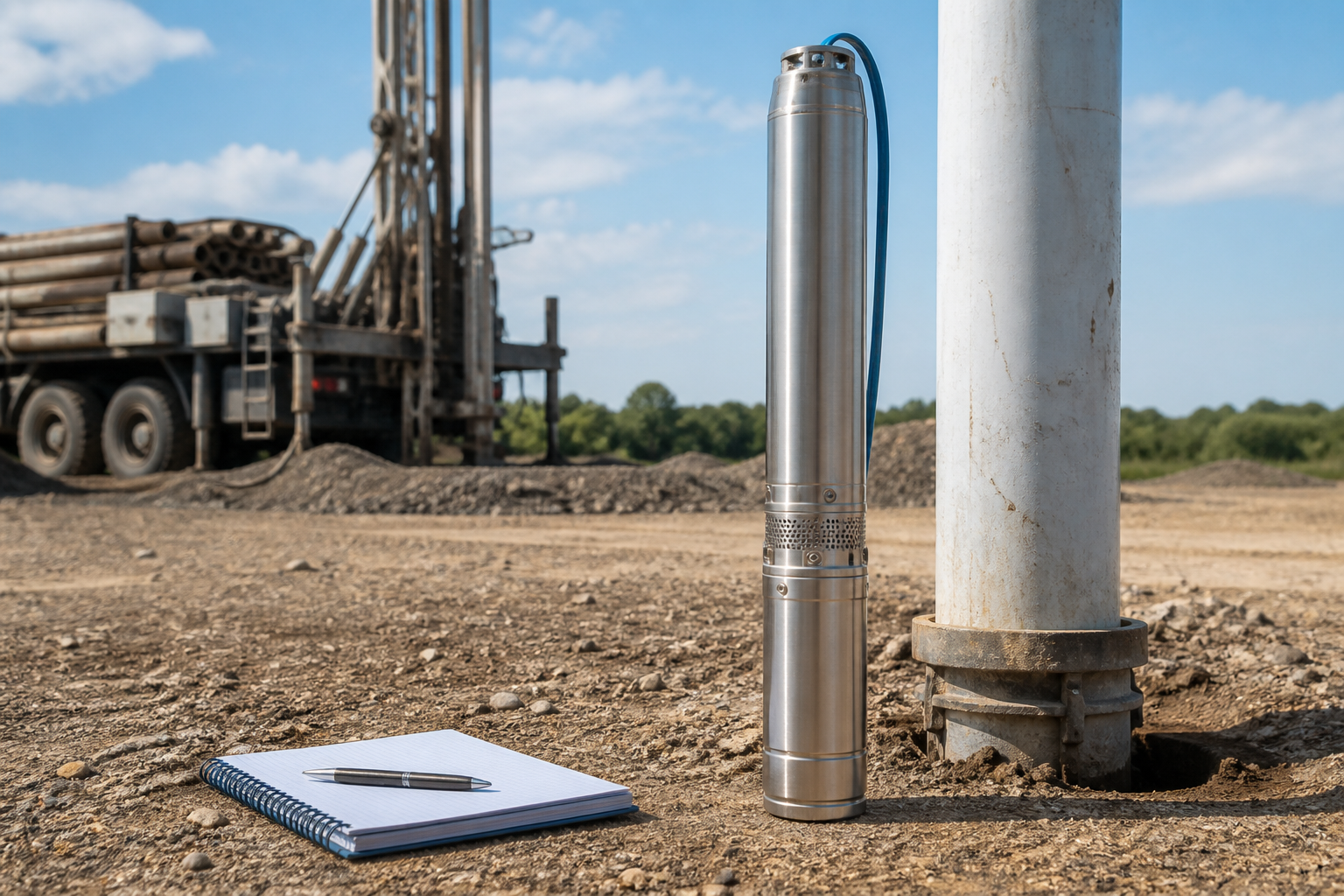
Irrigation, tank filling, geothermal or process supply may intentionally hold a stable duty for hours. A household pump that suddenly runs without stopping is different. Check whether demand is real, the pressure gauge rises, the pressure switch can reach cut-out, water is leaking, a valve is open, the check valve holds, the well level falls, and delivered flow meets the system. Do not leave an unexplained continuous run unattended; protect against dry running, overheating, overflow, and hidden pipe damage.
Check the well can sustain the flow
Measure or obtain the pumping water level and recovery at the intended withdrawal. The sustainable well yield can be lower than the pump's capacity. If the level declines toward the intake, the pump can entrain air, overheat, move sediment, or trip low-water protection. A smaller stable pumping rate into storage can serve peak demand more safely than repeatedly drawing beyond recovery. Revisit the well test when drought, nearby pumping, or long-term groundwater change is credible.
Table de décision
| Operating pattern | Interpretation | Required check |
|---|---|---|
| Planned long stable run | May be acceptable | Duty rating, cooling, curve and well yield |
| Unexpected run with pressure not rising | Likely system fault | Leak, level, valve, capacity and controls |
| Rapid start-stop cycles | Cycling problem | Tank, settings, leakage and sizing |
| Run ends on protection | Unsafe or abnormal condition | Water level, voltage, load and cooling |
Confirm hydraulic and motor load
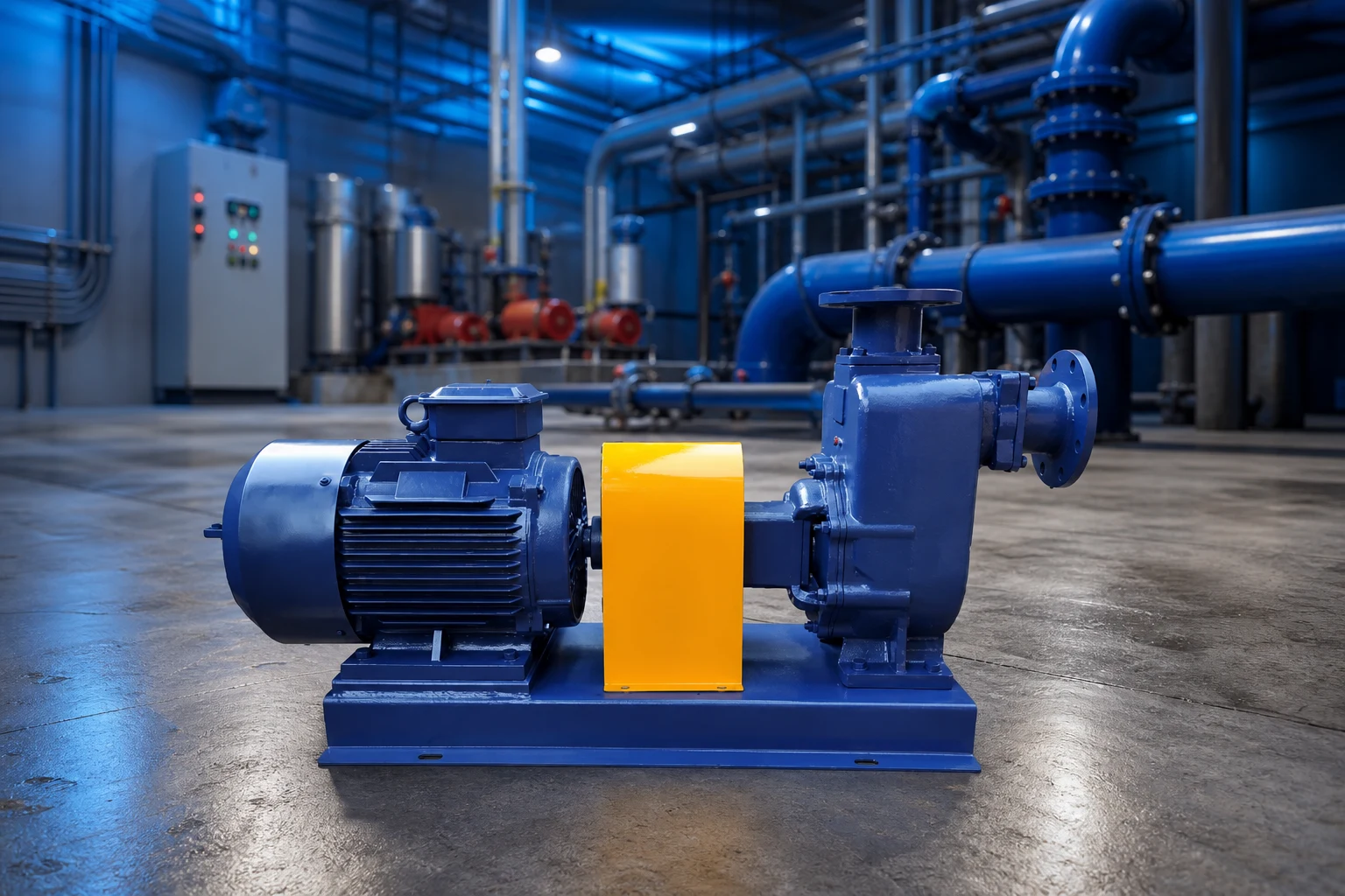
Calculate total dynamic head at the lowest expected water level and actual discharge condition. Plot the duty on the curve and review absorbed power, efficiency, minimum flow, runout, and motor load. Measure flow, pressure, voltage, current, water level, and temperature where applicable. A partly closed valve may reduce flow but can create an unsuitable low-flow condition; an open line may move the pump toward overload or excessive drawdown. The acceptable continuous region comes from the manufacturer, not a generic runtime answer.
Control cycling without creating another problem
Rapid cycling can be more damaging than a long stable run because it repeatedly heats the motor and stresses controls. Review pressure-tank drawdown, pressure differential, leaks, pump size, variable-speed settings, and storage. Do not widen pressure settings beyond equipment and fixture limits or disable minimum-speed, dry-run, or thermal protection. A cycle-stop or variable-speed arrangement requires coordinated hydraulic and motor review. The goal is a stable duty inside approved limits, not simply fewer starts.
Create an operating and alarm plan
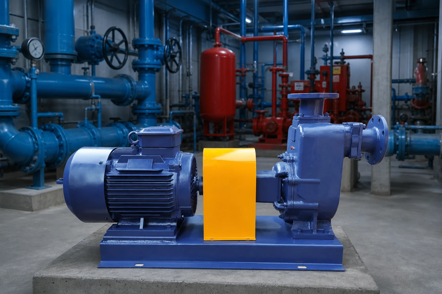
Record normal runtime, starts, flow, pressure, water levels, current, and protection events. Define alarms for low water, high or low pressure, overload, loss of flow, and excessive runtime when suitable. Test the response and make sure an alarm does not merely silence the pump without preserving essential water service or preventing damage. For critical supply, use storage or standby capacity and a documented response. Investigate changes promptly rather than increasing timer limits to hide them.
System selection, evidence, and procurement record
A well-pump decision should begin with the well record rather than the nameplate on the failed unit. Record drilled depth, casing diameter, static water level, pumping water level at a stated test flow, recovery, water quality, pump setting, rising-main size, pressure setting, storage volume, supply voltage, and the present control sequence. The pumping level—not the bottom of the well—is the starting point for the lift calculation. Add discharge pressure and pipe losses to establish total dynamic head, then compare the expected operating range with a current certified curve. The sustainable yield of the well can be lower than the short-term demand of the building. Storage and controls may therefore be more important than selecting a larger pump.
Treat electrical and hydraulic evidence as one record. Pressure, flow, water level, voltage, running current, starting behavior, insulation condition, runtime, starts, and controller events help separate a pump fault from a dry or declining well, leaking pipe, failed check valve, waterlogged pressure tank, obstructed line, low voltage, or incorrect control setting. Measurements must be made with suitable instruments by people qualified for the work. Never open energized equipment, pull a submersible pump, or enter a well enclosure without the required isolation, lifting plan, sanitation controls, and site procedure.
For procurement, ask every supplier to quote the same boundary: pump and motor, cable, splice, rising main, check valves, wellhead fittings, pressure tank, sensors, controller, protection, installation, lifting, testing, documentation, commissioning, and disposal of removed equipment. Compare the complete installed scope rather than the pump price alone. Require dimensional data, materials, curve, absorbed power, motor data, minimum submergence, cooling requirements, permitted starts, controls, installation instructions, test records, spares, and warranty conditions. At commissioning, preserve baseline readings so future diagnosis can distinguish normal aging from a changed well or system.
How this topic connects to BORRAPUMP equipment
This guide supports early review of how long can a well pump run continuously applications. It does not assign a final model. Send the liquid, flow range, total head, source and destination levels, solids, duty cycle, power, controls, site conditions, quantity, destination, and required approvals so equipment can be checked against the real service.
Guides d'ingénierie BORRAPUMP associés
Sources officielles et pour aller plus loin
U.S. Department of Energy pump systems; USGS groundwater levels; OSHA electrical safety. These sources provide general engineering, water, environmental, or safety context; current local rules, approved designs, and equipment instructions remain controlling.
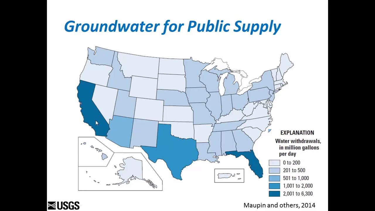
Educational video by U.S. Department of the Interior Museum: Groundwater: Unlocking the Mystery of an Unseen Resource.
Foire aux questions
Can a submersible well pump run all day?
Only when the exact pump and motor, cooling, submergence, well yield, operating point, and power meet their approved continuous-duty conditions.
Is continuous running worse than cycling?
Not necessarily. Rapid cycling can be highly stressful; both patterns must remain within manufacturer limits.
Why will my residential well pump not stop?
Possible causes include demand or leaks, low well level, failed valve, inadequate pump capacity, pipe loss, or control settings.
Will a larger pump solve long runtime?
Not automatically. It can increase drawdown and cycling unless well yield, head, storage, and controls are reviewed.
Final checkpoint
Before changing equipment or settings, reconcile the actual duty and site conditions with the approved curve, drawings, materials, power, controls, protection, installation, testing, and maintenance access. Record remaining assumptions and assign responsibility for closing them. Preserve the final readings and documents as the baseline for future inspection.
A useful handover also states what was not tested, which assumptions still depend on site confirmation, and when the next inspection is due. Identify the person responsible for water-level, pressure, flow, electrical, alarm, and maintenance records. Keep photographs and instrument details with the results. If a later reading is taken at a different valve position, source level, speed, pressure setting, or demand, label that difference before comparing trends. This simple discipline prevents a normal operating change from being mistaken for damage and prevents real deterioration from being dismissed as normal variation. When safety, sanitation, water supply, or property damage is at stake, define the temporary protection and escalation route before returning the system to unattended service.
Use the first verified operating record as a baseline, then compare future checks under the closest practical conditions. Note weather, liquid level, demand, valve positions, speed, filter condition, and any temporary hose or bypass. Confirm that gauges and meters have an appropriate range and that readings are taken from the same locations. A change in one number should trigger a review of connected evidence rather than an immediate part replacement. If the pump, motor, control, tank, valve, pipe, or source is changed, update the drawing and selection record. This keeps maintenance decisions tied to the real system and gives suppliers enough context to evaluate a warranty question, replacement, or operating adjustment without starting the investigation from zero.