Water hammer is a pressure transient caused by a rapid change in water velocity. In a booster pump system it can occur when a pump starts or stops, a check valve closes quickly, a motorized valve moves, or a column of water reverses. The result may be a bang, pipe movement, pressure spike, leaking joint, or repeated damage. Prevention starts with identifying the hydraulic path and the event that changes flow. A pressure vessel or soft start can help, but neither should be specified without checking the complete system.
Identify the event and the boundary
Record when the noise occurs: pump start, pump stop, lead change, power failure, valve closure, or a change in demand. Note the pipe length, diameter, elevation, fluid, normal velocity, valve type, check-valve location, and the pressure readings before and after the event. Long risers and fast closures often create more severe transients, but the actual wave and reflection behavior depends on the system.
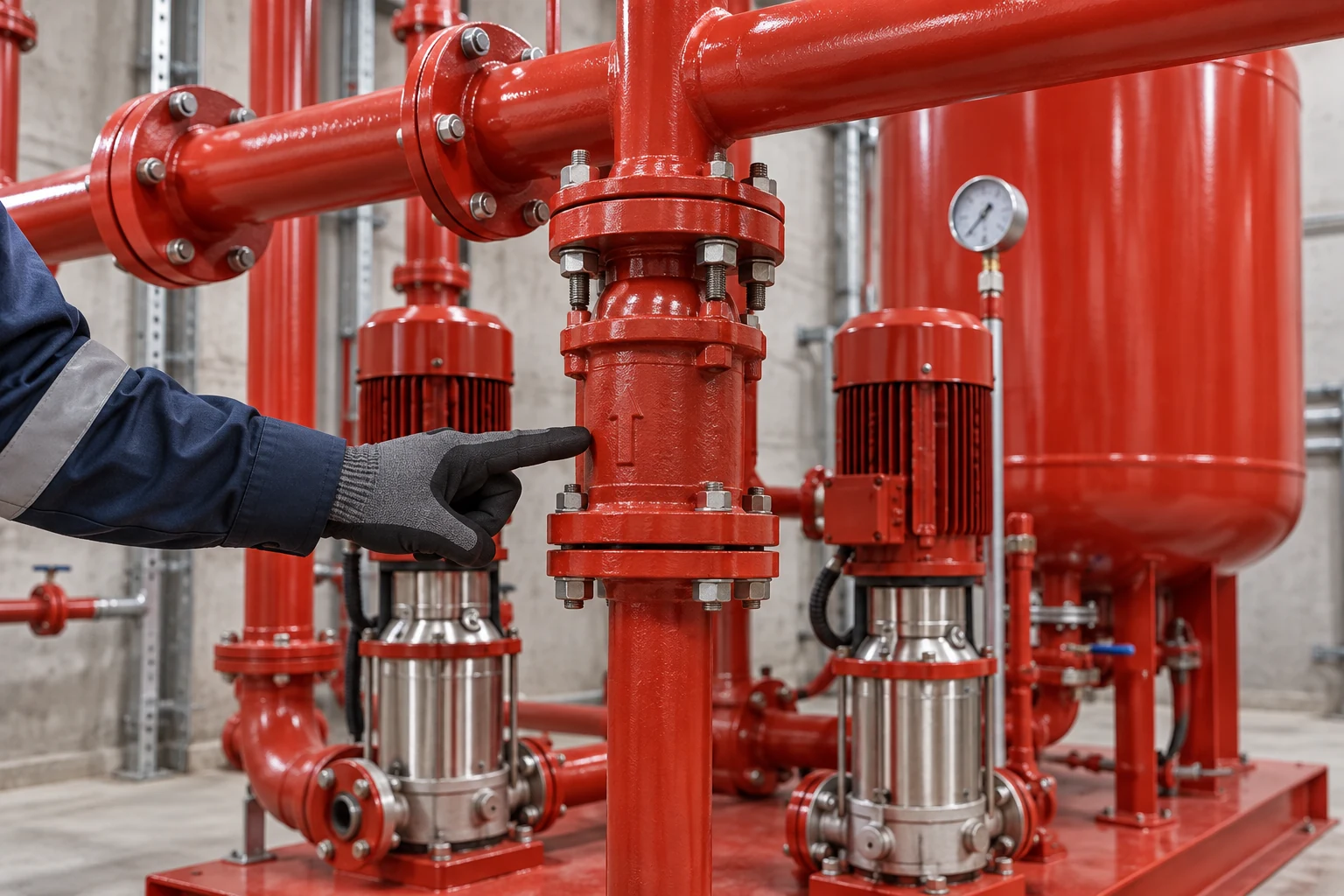
O BorraPumps booster-regulator package should be evaluated with its pressure vessel, pump curve, controls, valves, and piping boundary. The photograph of a red skid does not establish how a specific installation will respond.
Control velocity changes
Use a controlled acceleration and deceleration sequence where the pump and drive allow it. Avoid an abrupt stop that leaves a moving water column without a pressure path. A VFD can ramp speed, but the chosen ramp still needs to be checked against the motor, minimum flow, pressure target, and building response. The VFD selection guide explains why speed limits and sensor behavior must be set together.
Do not assume a long ramp is always safe. Too slow a ramp can cause low pressure or unstable staging, and the pump may spend too long near an unsuitable operating point. Test the start and stop transitions while recording pressure and pump state.
Review check valves and isolation valves
A check valve that closes late can allow reverse flow; one that slams can create a sharp transient. Select and install the valve for the actual flow direction, velocity, pressure, and maintenance arrangement. Verify that the disc or spring is not sticking and that the valve is not installed in turbulence that changes its behavior. Isolation valves should not be used as an improvised control device.
| Water-hammer risk | What to inspect | Possible design response |
|---|---|---|
| Pump stop causes a bang | Stop sequence, check valve, riser length | Ramp stop, suitable valve, transient study |
| Reverse flow before closure | Check-valve location and condition | Review valve type and closing response |
| Valve closure is rapid | Actuator timing and fail position | Controlled closure and safe interlock |
| Pressure vessel is ineffective | Connection, pre-charge, isolation | Verify vessel drawdown and location |
| Long high-rise column | Elevation, velocity, reflection path | Hydraulic transient calculation and protection |
| Repeated staging shock | Lead/lag sequence and ramps | Tune sequence and test transitions |
This is a screening checklist. A critical or complex system may need a qualified transient analysis and applicable code review.
Use a pressure vessel carefully
A properly connected pressure vessel can absorb a short transient and reduce starts, but its useful effect depends on volume, pre-charge, connection, isolation valves, and water-side condition. A waterlogged or isolated vessel provides little protection. Follow the vessel manufacturer’s depressurization and charging instructions and coordinate any change with the system designer.
O booster pump cycling guide explains why vessel condition also affects short cycling. A vessel should not be treated as a cure for a check valve that slams or a pump that stops abruptly.
Check supports, anchors, and flexible connectors
Transient forces can move a poorly supported pipe. Check anchors, guides, hangers, expansion allowances, and the loads transmitted to pump nozzles. Flexible connectors must match pressure, temperature, movement, and alignment requirements. They can isolate vibration and small movement, but they are not a substitute for a properly supported header.
Look for the physical evidence of a transient: witness marks, loosened fasteners, pipe movement, leaking gaskets, cracked supports, or a valve that changes position. Repair the mechanical issue before tuning controls.
Coordinate sensor and alarm behavior
Pressure sensors should see the controlled condition without excessive pulsation. The sensor placement guide explains why a poor measurement point can cause hunting and repeated starts. Define high-pressure alarms, low-inlet protection, loss-of-signal behavior, and restart after a power failure. A software alarm can warn an operator, but a mechanical or independent protective device may be needed for the identified hazard.
Commission the actual transitions
Test pump start, normal stop, lead change, standby start, power restoration, and a representative valve closure where permitted. Record pressure at the pump header and at critical remote points, along with speed, current, flow, and valve state. Repeat the test after tuning one parameter. Do not judge a transient only by whether the pump room sounds quiet; check the pipework, fixtures, and remote zones.

Prepare a supplier and installer record
Provide pump curves, flow and head, pipe sizes and lengths, elevation, valves, check-valve data, pressure-vessel data, drive ramps, control setpoints, and the transient events that matter. Request confirmation of assumptions and a commissioning sequence. The BorraPumps water-supply range can identify candidate packages, while the installed piping and controls determine the final response.
Consider emergency and maintenance modes
The transient response may be different when one pump is isolated, a standby pump starts, or the building loses normal power. Include these cases in the design narrative. A bypass that appears useful during maintenance can create an abrupt flow path if its valve is opened quickly. Label manual steps, interlocks, and safe valve positions so an operator does not create a transient while trying to restore service.
Keep a commissioning baseline
Record the pressure trace, valve positions, drive ramps, pump sequence, check-valve orientation, vessel condition, and remote-point observations after the system is accepted. Review the baseline after major pipework, pump, control, or occupancy changes. Water-hammer prevention is an operating discipline as well as a hardware selection.
Review the pressure zones and remote users
A transient that is small at the pump header can be more severe at a high point, a long branch, or a downstream pressure-reducing valve. Map the remote points that matter and consider where pressure should be measured during commissioning. The pump-room gauge alone cannot show every reflection or local pressure spike. Coordinate the response with plumbing, controls, and structural designers.
If the building contains sensitive fixtures or long risers, document the reason for the selected valve closure time, drive ramp, vessel, and support arrangement. Keep assumptions visible. When occupancy, pipework, or pump capacity changes, revisit the transient risk instead of assuming the original settings remain valid.
Make operator actions unambiguous
Label normal and maintenance valve positions and include the sequence in the operator handover. If a manual valve must be opened slowly or a pump must be started in a defined order, write that step plainly. Clear instructions reduce the chance that a well-intentioned recovery action creates a new pressure transient.
Reassess after future upgrades
Adding a larger pump, extending a riser, changing a check valve, or increasing the control setpoint can change the transient even when the original skid remains in place. Keep the hydraulic assumptions with the equipment record and review them at design changes. A short commissioning test after an upgrade is cheaper than discovering the new pressure pulse through a failed joint.
Include a clear acceptance limit
The acceptance record should state the measured pressure behavior and the conditions under which the system was tested. If a limit comes from a code, equipment manual, or transient study, cite that source. Do not replace a documented limit with the informal statement that the pipe “sounds fine.”
Confirm the field valve lineup
The acceptance record should identify each isolation and check valve position used for the test. A different lineup can create a different transient, so the operator needs enough detail to reproduce the safe condition during future maintenance.
Engineering sources
O US Department of Energy pumping-system sourcebook e ASHRAE variable-speed pumping guidance provide general pump and control context. A critical installation may need a project-specific transient study and code review.
Perguntas frequentes
Is water hammer only caused by a pump stopping?
No. Rapid valve closure, check-valve action, power loss, reverse flow, and pump starts can all change velocity and create a transient.
Can a VFD eliminate water hammer?
It can reduce some pump-related transients when correctly selected and tuned, but it cannot correct a slamming check valve, unsupported pipe, or unsuitable valve sequence.
Where should a pressure vessel be installed?
At a point where it can respond to the transient and remain hydraulically connected. The volume, pre-charge, connection, and isolation arrangement must follow the project and manufacturer requirements.
What proves that the solution works?
Repeat the defined start, stop, staging, and power-loss tests while measuring pressure and inspecting the piping and remote service points. Document the final settings and observations.
Further learning
The NPTEL IIT Kharagpur lecture on pump characteristic curves is useful background for understanding why the installed system can behave differently from a catalogue point. It is educational material, not a substitute for the selected pump manual, project calculations, or local code review.