
Centrifugal pump sizing for water transfer starts with the amount of water that must be moved, the available transfer time and the total head at that flow. It then checks suction conditions, the pump curve, motor loading and the range of operation. Selecting by outlet diameter, maximum head or motor power alone can produce a pump that misses the duty or operates poorly. For a tank-to-tank project, build a clear duty specification before requesting a quotation. This guide shows how to organize the inputs, perform transparent illustrative calculations and verify the final selection without inventing product performance.
Define the transfer task before calculating head
Write down the source, destination and reason for the transfer. A storage tank replenished once per shift has a different demand pattern from a process that needs continuous supply. Identify the required usable volume, transfer window and any inflow or outflow occurring during the operation. Distinguish total tank capacity from the amount that actually needs to move. Include planned downtime or availability limits when they affect the transfer window.
For a simple batch with no simultaneous flow, required average flow is volume divided by time. For example, transferring 60 cubic metres in two hours requires an average of 30 cubic metres per hour. This is an illustrative requirement, not the rating of any BorraPumps model. If the receiving process consumes water during filling, include that demand in the water balance rather than using the batch calculation unchanged.
Do not silently add a large safety factor to every input. Identify uncertainties explicitly: future demand, level variation, fouling allowance and measurement accuracy. Agree an appropriate design basis with the project team. Repeatedly adding unrelated margins can create an oversized unit whose normal operating point is far from the intended region.
Separate static head from flow-dependent losses
For two open tanks, the difference between their water-surface elevations establishes the static elevation component. Use the source’s lowest planned level and destination’s relevant level when reviewing the demanding case. The elevation of the pump itself matters for suction analysis but does not automatically become an additional static head term between tank surfaces. Define a consistent reference elevation and keep a sketch with the calculation.
If either vessel is pressurized, include the pressure difference expressed as head for the liquid. A free discharge, nozzle or downstream device may require a different boundary definition from an open receiving tank. Include the relevant velocity term where the energy balance requires it. Do not mix a tank-surface calculation with nozzle pressure readings without accounting for their different boundaries.
Friction and fitting losses vary with flow. Measure the actual route, internal diameter, material, valves, strainers and fittings. A temporary hose with an uncertain internal diameter or kinked routing can have quite different losses from a straight permanent pipe. The US Department of Energy pumping-system sourcebook explains the interaction of the pump and piping system; it supports checking the route rather than treating pump selection as a standalone catalogue exercise.
Build a duty table with visible assumptions
| Entrada | O que gravar | Why it changes selection |
|---|---|---|
| Transfer volume and time | Usable batch volume, available hours and simultaneous demand | Defines required flow rather than an arbitrary pump capacity |
| Source and destination levels | Minimum and maximum operating water surfaces on a common datum | Defines the static-head range |
| Piping route | Lengths, internal diameters, fittings, valve states and hose details | Defines flow-dependent losses |
| Water conditions | Temperature, suspended material and compatibility requirements | Affects suction analysis, construction and service suitability |
| Fonte de alimentação | Voltage, frequency, phase, starting constraints and control method | Determines whether the proposed drive can start and operate correctly |
| Operating pattern | Hours, starts, changing tank levels and low-demand periods | Defines the required operating range and control needs |
This is a project input checklist, not a table of assumed manufacturer specifications. Keep each value traceable to a survey, drawing, process requirement or supplier document. Mark missing information as missing; replacing it with a plausible-looking number makes the quotation appear more certain than it is.
Use a transparent example to check units
Consider an illustrative duty of 30 cubic metres per hour between open tanks. Suppose the agreed elevation difference at the selected level condition is 12 metres, and a separate route calculation gives 8 metres of friction and fitting losses at that flow. If the boundary has no additional pressure or significant velocity requirement, the illustrative total head is 20 metres. The 8-metre loss is an assumed example input, not a calculated value for an unspecified pipe.
For hydraulic power, use P = rho × g × Q × H. With water density approximated as 1,000 kilograms per cubic metre, g = 9.81 metres per second squared, Q = 30/3,600 cubic metres per second and H = 20 metres, the result is about 1.64 kilowatts. This is hydraulic power delivered to the liquid. It is not the required motor nameplate rating or electrical consumption.
If an illustrative pump efficiency were 65 percent, shaft power at that single point would be approximately 1.64/0.65 = 2.52 kilowatts. The assumed efficiency is only for arithmetic. Obtain actual power information across the approved operating range, then check motor selection, service conditions and control requirements with the supplier. Include motor and drive efficiency when estimating electrical input; do not divide by an invented catalogue efficiency and call the result verified consumption.
Find the operating point on a configuration-specific curve
Request the curve for the offered model, speed and impeller diameter. The required point must fall within an acceptable region of that curve, but the installed operating point also depends on the system curve. Use the pump duty-point calculation guide to understand that intersection. A pump chosen only because its maximum flow exceeds the target can still fail to deliver the required head at that flow.
Review several cases: lower and higher source levels, receiving-level changes, expected valve positions and credible route variation. A fixed-speed pump may deliver different flow as those conditions change. If transfer time must stay consistent, evaluate controls and measurement rather than assuming a single rated point will maintain it. Avoid interpreting a variable-speed drive as permission to run at any speed without model-specific limits.
O centrifugal pump curve guide explains head, efficiency and power information. Ask which curve revision supports the quotation and whether the stated performance is guaranteed under agreed conditions. Keep that revision with the purchase record so later installation changes can be assessed against the actual selection.
Check suction availability independently
Suction conditions are a separate selection check. Determine source pressure, lowest liquid level relative to the pump, water temperature, site elevation and inlet losses. Compare calculated NPSH available with the selected pump’s NPSH requirement and the appropriate margin. The Hydraulic Institute explanation of NPSH and operating regions describes why adequate margin and a suitable operating region matter for reliability.
Do not assume that a self-priming capability, flooded suction or a large inlet guarantees acceptable suction performance. An intake vortex, dirty strainer or a changed hose route can still cause problems. Use the NPSH available versus required guide for the calculation framework, then obtain the exact product data. If the source levels or temperatures are unknown, keep the selection provisional until they are defined.
Confirm product and drive suitability
O BorraPumps ISW horizontal pump product page provides a relevant clean-water product family for a supplier enquiry. It does not establish a suitable model for the illustrative 30-cubic-metre-per-hour duty above. Ask for the configuration, curve, construction, liquid limits and installation instructions applicable to your project. Use a different supported product family when the liquid or installation requires it.
Confirm supply voltage, frequency and phase, as well as starting method, available electrical capacity and environmental conditions. Check whether the motor can cover the expected operating range without overload. Include protection and isolation in the installation plan. Maintenance preparation should follow the approved procedure and the HSE electrical isolation guidance; a hydraulic sizing calculation does not authorize wiring or energizing equipment.
Make installation assumptions part of the quotation
Show the intended pump location, piping route, supports and access space. State whether the source can run low and how the system should respond. Identify discharge destinations and any backflow or surge concerns that need a project review. Do not ask a supplier to infer these from a photograph of a tank. A simple measured sketch with defined boundaries is often more useful than a large collection of unlabelled site pictures.
Include the required monitoring and acceptance process in the enquiry. Decide how flow will be measured, where pressure readings will be taken and what conditions will be recorded during testing. If only a timed tank-volume test is practical, describe the limitations and simultaneous flows. A commissioning method agreed before purchase reduces disputes about whether the selected pump meets the requirement.
Verify the installed duty and keep a baseline
During authorized commissioning, record actual levels, valve states, flow, pressures, speed and electrical observations. Compare them with the agreed duty and curve. If results differ, check instrumentation, route changes and liquid conditions before assuming the pump is defective. Preserve both the original calculation and the as-built route; editing the calculation to match an unexplained result hides a potentially important issue.
After acceptance, keep a baseline for later maintenance. Increasing transfer time may indicate a changed system, wear or an inlet restriction rather than an undersized original selection. Repeated measurements under comparable conditions make that distinction easier. Reassess the duty before adding more equipment when the process expands, because the piping and suction conditions may also need changes.
Learn how the curve connects to the calculation
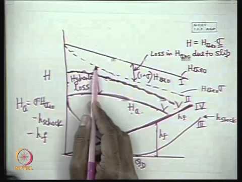
The NPTEL lecture below explains centrifugal-pump characteristics and supports the curve-reading step. It is general engineering education and does not replace a supplier’s model-specific selection or the project’s acceptance requirements.
Perguntas frequentes
Can I size a water-transfer pump from motor power alone?
No. Define flow, total head, suction conditions and operating range, then use the configuration-specific curve and power data to check the drive.
Is the height of the discharge pipe the total head?
Not by itself. The boundary elevation difference, pressure conditions and flow-dependent losses must be included consistently.
Should I choose a much larger pump for future demand?
Document the future case and compare both present and future operation. Oversizing without an operating-range review can reduce efficiency and reliability.
Does the calculation prove that a specific ISW model is suitable?
No. The example demonstrates units and workflow. A specific model needs supplier performance data and checks against the actual installation.
What should I send with a quotation request?
Send the liquid description, required flow and head cases, source levels, temperature, route sketch, power supply, operating hours and proposed acceptance method.