
The correct centrifugal pump rotation direction is the direction specified for the exact pump assembly, viewed from the reference end stated by its manufacturer. Confirm the casing or assembly arrow and the approved manual; do not assume that every pump turns clockwise. A pump running backwards may still move some water, so discharge flow alone does not prove correct rotation. The verification must follow an approved commissioning procedure that protects people, keeps the pump within its operating requirements, and prevents an automatic or remote start while equipment is being inspected.
Start with the pump arrow and the viewing position
Clockwise and counterclockwise have meaning only when the observer’s position is defined. Looking toward a shaft from the opposite end reverses the apparent direction. Record whether the manufacturer’s instruction is viewed from the motor end, the coupling end, or another stated position. A handwritten “CW” without that information is an incomplete commissioning record.
Locate the actual rotation marking and compare it with the manual for the supplied unit. A separate arrow may indicate liquid flow rather than shaft rotation. Do not confuse a nozzle flow arrow, a casting mark, or a fan-cover feature with the required pump direction. If the marking is missing or contradictory, obtain clarification from the supplier before starting the assembly. Guessing from a photograph of another pump is not an acceptable substitute.
Identify the complete drive arrangement
An electric motor, a diesel engine, and a belt-driven assembly need different checks. A directly coupled motor and pump share a mechanical relationship, but the direction must still suit the pump. A gearbox or belt arrangement can change the relationship between driver and driven shafts. Equipment that appears similar from outside can therefore require different documentation.
For a close-coupled pump, the impeller may be inaccessible without dismantling. For a submersible unit, the rotor cannot normally be watched during operation. Ask for the approved verification method for that particular assembly rather than applying an open-coupling method everywhere. A field procedure should identify the equipment, observation method, permitted operating condition, and responsible people.
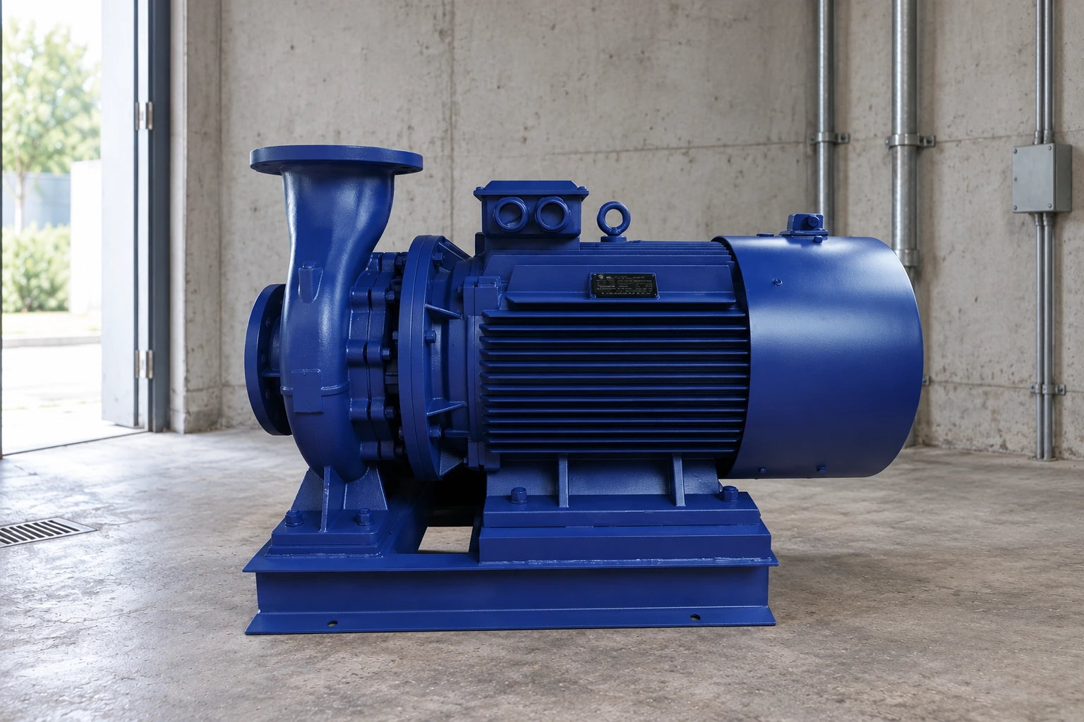
O ISG vertical inline pump is an example of an inline product family for which the supplied manual and markings should govern. Its shape does not establish the direction for every variant or explain how to check a particular installation safely.
Make the inspection safe before approaching the equipment
Inspecting an arrow, removing a cover, or working around a coupling can expose people to rotating parts or electrical hazards. Follow the site’s isolation procedure, prevent remote and automatic operation, and verify the safe condition before work begins. The UK Health and Safety Executive explains the need to isolate electrical equipment before maintenance. Isolation is a task-specific control, not merely selecting “off” on a screen.
Hydraulic energy also matters. Pressure, stored liquid, a raised water column, or flow from another operating pump can remain after the motor is stopped. Consider whether the shaft could move because of reverse flow through the system. The approved work plan must address the actual energy sources and the condition in which the observation will be made.
Do not remove guards from operating equipment to obtain a better view. Any temporary test arrangement, coupling work, or restoration of a guard belongs to a controlled procedure performed by competent personnel. This article identifies the checks to request; it does not authorise improvised access to a rotating shaft.
Use the manufacturer’s commissioning method
Some assemblies allow driver direction to be checked while uncoupled, under a defined procedure. Others require a different method or specific preparation before any rotation. A “quick bump” is not universally harmless: a pump may require liquid, lubrication, a completed seal system, or a particular mechanical condition before it turns. Obtain the applicable instructions and observe their restrictions.
Before an authorised test, confirm the intended start command, stopping method, observation location, and exclusion zone. Check that the equipment cannot restart unexpectedly after the test. If a drive can start from multiple control points, the procedure must address all of them. Record the observed direction using the same viewing position as the manufacturer’s reference.
After the test, restore the safe condition before making any adjustment. Do not make repeated starts merely to resolve an ambiguous observation. The correct response to uncertainty is to improve the verification method and documentation, not to increase exposure or repeatedly operate an unconfirmed assembly.
Do not diagnose direction from pressure alone
A centrifugal impeller rotating in reverse can sometimes develop reduced flow and pressure. The amount depends on the impeller and casing geometry, speed, and system. Consequently, seeing water at a discharge is insufficient evidence. Equally, low pressure has many other causes, including an incorrect duty, air ingress, suction restrictions, low speed, worn components, or an inaccurate gauge.
Compare observations with the approved curve after rotation has been independently confirmed. The pump curve guide helps distinguish the required flow and head from a vague expectation of “strong pressure.” The water-transfer troubleshooting guide covers a wider diagnostic path when the measured duty remains incorrect.
The Engineering Mindset’s centrifugal pump basics explains how the rotating impeller transfers energy to liquid. That hydraulic background supports the importance of direction; it does not replace the manufacturer’s instructions for a specific motor, impeller attachment, or commissioning test.
Treat a phase-sequence indication as part of the evidence
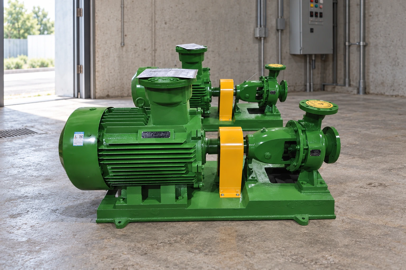
For a three-phase installation, the supply and connections affect motor direction, but the complete assembly still needs an approved verification. A phase-sequence instrument indicates the sequence at its measurement point. It does not, by itself, prove that the pump turns correctly after every internal connection, drive, and mechanical element is considered.
Any electrical correction must be performed by qualified personnel under isolation and in accordance with the equipment documents. Do not interchange conductors casually at a live terminal or assume that a change appropriate to a conventional motor is appropriate to every electronic drive. Single-phase motors and engine-driven pumps require their own arrangements; generic three-phase advice cannot be transferred to them.
Following an electrical repair, motor replacement, drive replacement, or cable change, review whether direction must be reconfirmed. Retain the test result with the maintenance record so future technicians know what was checked and from which viewing position. A label from an old configuration is not proof for a newly modified assembly.
Keep commissioning evidence in a simple record
| Record field | O que capturar | Porque é que isso importa |
|---|---|---|
| Assembly identity | Pump, driver and drive models; document revision | Links the result to the installed equipment |
| Required direction | Manufacturer marking and defined viewing end | Removes clockwise/counterclockwise ambiguity |
| Test preparation | Isolation, hydraulic condition and approved procedure | Shows that the verification method was appropriate |
| Observed result | Direction, observer location and method | Establishes what was actually verified |
| Restauração | Guards, coupling work, controls and final checks | Evita que um sistema de teste incompleto entre em serviço |
Utilize o registro para identificar informações que ainda não estão disponíveis antes do início da operação. Não substitui um procedimento de segurança aprovado ou um formulário de aceitação específico para o modelo. Se um fornecedor testemunhar a comissionação, ambas as partes devem identificar quaisquer pontos não resolvidos, em vez de considerar toda a montagem como aceita, pois o motor funcionou por pouco tempo.
Verifique as consequências após a rotação incorreta
Se a bomba já estiver operando na direção errada, pare e avalie de acordo com as instruções do fabricante. Não assuma que mudar a direção restaurará imediatamente uma máquina intacta. Dependendo do design, a operação reversa pode afetar a fixação do rotor, a disposição da vedação, o sistema de lubrificação ou outros componentes. A extensão da inspeção deve refletir a construção específica e o histórico do evento.
Registre a duração, se conhecida, a condição do líquido, a velocidade, os sintomas, as viagens e quaisquer ruídos ou vazamentos anormais. Pergunte ao fornecedor quais inspeções são necessárias antes de reiniciar o funcionamento. Evite apresentar uma teoria não comprovada como uma falha confirmada: um som incomum durante o evento é uma observação, enquanto uma componente danificada requer inspeção ou outras evidências.
Após a montagem estar pronta para operação, conclua os demais testes de comissionamento. A rotação é apenas um ponto de verificação. Prime ou preencha conforme necessário, verifique a condição de sucção, verifique as posições das válvulas aprovadas e confirme a carga, a corrente, a condição de vazamento e as funções de proteção. Guia de instalação e alinhamento interno aborda os registros de instalação que devem acompanhar esse processo.
Aprimoramento
O módulo “Mod-01 Lec-15 Características de uma bomba centrífuga” do NPTEL fornece informações sobre o desempenho da bomba centrífuga. Utilize-o para compreender por que as medições de desempenho pertencem a uma configuração operacional conhecida. Trata-se de material educativo, não de instruções para expor peças rotativas ou para ativar uma instalação ainda não concluída.
Perguntas frequentes
As bombas centrífugas são todas no sentido horário?
Não. Utilize a marcação e a documentação para a montagem exata, com o fim de visualização definido. Uma orientação memorizada em outra máquina não é prova suficiente para uma nova instalação.
O fluxo de água prova que a rotação é correta?
Não. Algumas bombas ainda podem mover o líquido em rotação inversa. Confirme a direção pelo método aprovado e compare então a carga operacional medida com a curva de desempenho correta.
Posso verificar a direção ao ligar brevemente uma bomba vazia?
Siga apenas o procedimento aprovado pelo fabricante. Alguns equipamentos podem ser danificados por rotação seca ou por partida antes de as instalações de lubrificação e vedação estiverem prontas. Não assuma que uma duração curta elimina esse risco.
Um medidor de fase-séquencia substitui a verificação de comissionamento?
Não. Ele fornece informações elétricas úteis no ponto de medição, mas a direção final da montagem instalada ainda precisa ser verificada por meio de um método adequado. O pessoal qualificado deve gerenciar quaisquer alterações elétricas.
O que deve acontecer após a substituição do motor?
Leia os documentos de montagem, verifique as alterações de conexão, a verificação de rotação necessária e os demais requisitos de comissionamento. Registre a nova verificação com o motor substituído, em vez de confiar no resultado do teste do motor anterior.