
Pump vibration measurement is useful when the sensor location, direction, mounting method, instrument settings and operating condition are recorded consistently. A number taken from an arbitrary point on the casing cannot reliably identify a bearing defect or prove that a pump meets an acceptance standard. Establish an approved measurement route, collect a baseline at a known duty, and compare like with like before choosing corrective work.
This guide covers planning and documenting measurements on industrial water-pump installations. It does not supply a universal alarm limit or authorize working beside unguarded rotating parts. Machine protection settings and acceptance criteria require the applicable equipment documentation and responsible engineering review.
Separate a screening reading from a diagnostic survey
A handheld overall reading can identify a change that deserves investigation. A diagnostic survey may additionally require spectra, time waveforms, phase, speed references or specialist bearing measurements. These are different levels of evidence. An overall value alone cannot distinguish all possible hydraulic, structural, mechanical and electrical sources.
O Hydraulic Institute discussion of pump vibration explains amplitude, frequency, measurement units and the interaction between forcing frequencies and structural response. It supports a disciplined investigation rather than a one-number diagnosis. Decide what the survey needs to answer before selecting the sensor and recording settings.
For example, a maintenance route may ask whether a bearing housing has changed from its healthy baseline. A commissioning survey may ask whether an installed pump meets a contractual criterion. A specialist investigation may ask whether a speed-dependent response involves resonance. The data requirements and acceptance documents differ, so state the purpose at the top of the report.
Define equipment and measurement locations
Create a route drawing or annotated photograph that identifies the pump, driver, bearing housings and accessible measurement points. Give each point a stable name so different technicians return to the same location. Where the equipment permits it, measurements on rigid bearing-related structures are generally more useful than readings on thin covers or guards that can respond differently from the underlying machine.
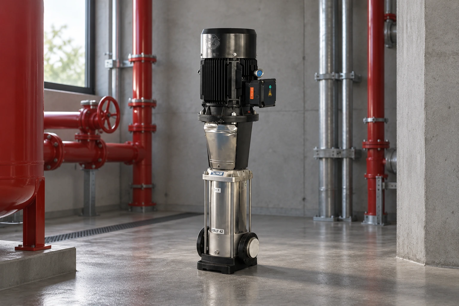
Choose the route with the equipment manufacturer or a competent vibration specialist. Vertical and horizontal machines have different structural behavior and access constraints. A submersible pump may not permit the same measurements as an exposed end-suction pump. Do not assume a motor-top reading is interchangeable with a pump-bearing reading or invent access to an underwater bearing.
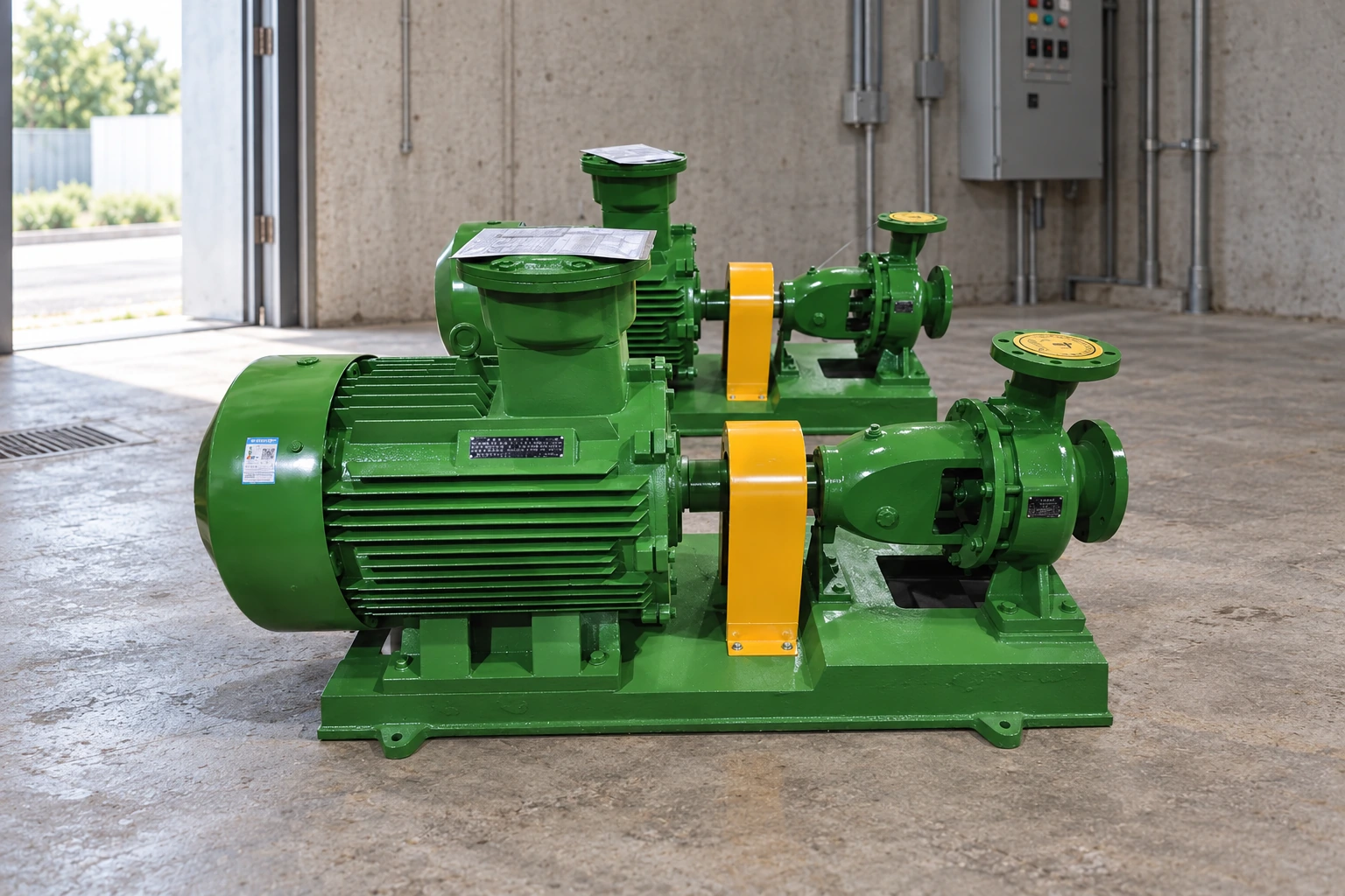
O IS clean water centrifugal pump range e Bombas horizontais em linha ISW illustrate why the actual assembly and support arrangement must be identified first. These product references do not establish that any particular sensor location or monitoring accessory is supplied. Use the delivered package drawing and safe access assessment for the final route.
Record direction and sensor mounting
For a horizontal shaft, route labels commonly distinguish horizontal radial, vertical radial and axial directions. Define those directions on the route drawing. A description such as “pump side” is ambiguous and can lead to comparisons between different structural responses. For a vertical shaft or unusual arrangement, define equivalent directions explicitly instead of copying horizontal labels without thought.
Sensor mounting affects the frequency response and repeatability of the measurement. Stud mounting, adhesive pads, magnets and handheld probes have different limitations. Select a method appropriate to the instrument, surface and frequency range. Do not compare a loosely held probe measurement with a previous stud-mounted reading as though the collection conditions were identical.
Prepare the permitted contact surface, check cable routing and prevent contact with moving or hot components. Keep guards in place. If installing a permanent pad or sensor requires intrusive work, use the approved shutdown and isolation procedure. Sensor access should never depend on reaching through a coupling guard or leaning across an exposed shaft.
Keep units, amplitude definitions and bandwidth together
| Recorded quantity | Typical reporting form | Information that must accompany it | Comparison error to avoid |
|---|---|---|---|
| Housing velocity | Velocity with an amplitude convention such as RMS | Units, frequency band and sensor location | Comparing RMS with peak values |
| Displacement | Displacement with peak or peak-to-peak stated | Measurement type, frequency band and direction | Treating shaft-relative and housing motion as equivalent |
| Acceleration | Acceleration with the instrument’s stated convention | Units, processing and bandwidth | Comparing a high-frequency metric with overall velocity |
| Spectrum | Amplitude against frequency or orders | Speed, frequency span, resolution and amplitude definition | Assigning a fault from a peak without operating context |
| Trend | Repeated observations of the same metric | Identical route, settings and comparable duty | Treating a changed collection method as machine deterioration |
The Hydraulic Institute source above explains why amplitude definitions matter. This table deliberately gives no universal severity threshold. A value can only be assessed against a criterion that applies to the machine type, measurement quantity, support condition and purpose of the test.
A report that says only “vibration increased” is incomplete. It should identify which metric increased, at which point, under what duty and by how much relative to a comparable baseline. Preserve the original units and instrument output. Conversions should be documented, and conversions between displacement, velocity and acceleration require frequency information and an appropriate signal assumption.
Measure the operating condition alongside vibration
Record pump speed, flow, suction and discharge pressure, fluid temperature where relevant, and the number of pumps operating. Add valve configuration, tank levels or other system conditions that affect duty. A variable-speed pump can show different vibration simply because its speed or hydraulic operating point has changed.
O Vibration Institute discussion of pump monitoring emphasizes collecting hydraulic operating information with vibration and using comparable conditions for periodic data. That connection matters because low flow, cavitation and other hydraulic disturbances can affect the signal without a bearing being the original cause.
Use o best efficiency point guide to place the operating point in context, and the flow measurement methods guide to plan reliable flow observations. These checks complement vibration measurement. They do not mean a pump should be forced to a different flow during a test without an approved operating plan.
Establish a useful baseline
Collect a baseline after the installation has completed its required alignment, support, lubrication and commissioning checks. Describe the condition of the machine and unresolved exceptions. A baseline recorded while the pump is already cavitating or operating with a known support defect should not be labeled healthy simply because it is the earliest reading available.
Record the instrument model, sensor identification, calibration status, mounting method, settings and route version. Store the original data files rather than only a screenshot or a handwritten final value. If a route point cannot be reached safely, mark it unavailable and explain why. Substituting another convenient point without recording the change creates a misleading trend.
Use repeated observations under stable approved conditions to assess collection repeatability. If readings vary unexpectedly, first examine mounting, speed, process fluctuation and measurement settings. A noisy measurement method can produce a false maintenance alarm. The objective is a trustworthy reference that another trained technician can reproduce, not simply a long list of numbers.
Interpret changes without assigning a premature fault
An increase near rotational frequency may guide investigation toward certain mechanical or structural conditions, but it is not proof of one cause. Harmonics, hydraulic forcing, resonance and changes in support stiffness can complicate the response. Diagnosis should combine frequency information, directions, operating conditions and relevant physical checks.
For example, a measurement that changes when flow changes deserves hydraulic investigation. A response that varies sharply over a speed interval may require a dynamics assessment. A persistent change following maintenance may justify reviewing alignment, support and assembly records. These are investigation paths, not automatic instructions to change bearings or tighten anchors.
Nosso centrifugal pump bearing failure guide addresses bearing-related evidence separately. Use that article when the collected data and inspection support a bearing investigation. Avoid describing every high-frequency signal as bearing damage; hydraulic disturbances and collection problems can lead to misleading impressions.
Select the correct acceptance and alarm criteria
Determine whether the test is a factory acceptance check, an installed commissioning check or an in-service condition trend. Identify the applicable standard edition and equipment classification, along with any contractual or manufacturer requirements. Confirm whether the criterion refers to bearing housing motion, shaft motion or a specific instrument metric.
Do not adopt a numerical limit from a different pump merely because the motor power appears similar. Support stiffness, machine arrangement, speed, measurement location and the purpose of the criterion can affect applicability. The responsible engineer should document the selected basis and any exceptions before testing. If a standard is not available, do not invent its limits from an online summary.
Trend alarms and protective shutdown settings also require different decisions. A trend alert may initiate inspection, while a protection function can stop equipment and affect the process. Any change to protection requires the site’s authorized review. A maintenance article or handheld instrument’s generic color display is not sufficient authority to alter those settings.
Turn the survey into a maintenance decision
The final report should state whether the observations are comparable with the baseline, whether the selected criterion applies, what changed and which follow-up is justified. Include missing data and operating differences that limit the conclusion. If uncertainty remains, define the next measurement that would distinguish the leading explanations.
After corrective work, repeat the relevant route under comparable approved conditions and retain both datasets. Report whether the measured change improved, remained or moved to another point. Replacing a component is an action; the follow-up measurements are evidence of the result. Preserve that distinction in the maintenance history so the next investigation starts from reliable information.
Aprimoramento
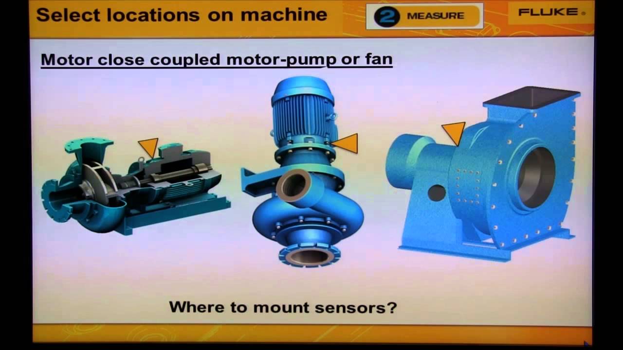
Fluke Corporation’s educational video “Vibration Testing: How to Select Correct Measurement Locations on a Machine” discusses measurement location selection. It is included for measurement technique, not as an endorsement of an instrument or a source of pump-specific alarm settings. The channel supplies test instruments rather than competing pump packages.
Perguntas frequentes
Where should pump vibration be measured?
Use approved, repeatable locations identified on the actual machine, commonly on rigid bearing-related structures where safely accessible. Define the location and direction precisely; arrangements differ between pump types.
Can I compare two readings with different units?
Not directly. Confirm the measured quantity, amplitude convention, bandwidth and location. Conversions between motion quantities require appropriate signal and frequency information, not only a unit multiplier.
Does high vibration prove bearing failure?
No. Hydraulic conditions, alignment, support, resonance and collection errors can also affect vibration. Diagnose using operating data, detailed measurements and appropriate inspection.
Is one acceptable vibration limit valid for all pumps?
No. Select the applicable equipment criterion and measurement method before assessing the result. A generic threshold cannot establish compliance for every machine and support arrangement.
What should accompany a vibration trend?
Keep the point and direction, sensor mounting, instrument settings, units, speed, flow and pressure with each reading. Record route changes and missing measurements so the comparison remains meaningful.