Sewage pump float-switch placement must provide repeatable start, stop and alarm signals while keeping every float clear of the inlet, walls, pump, cables and lifting chains. Level settings depend on the wet-well geometry, pump cooling limits, inflow, desired cycle and emergency response time. There is no universal spacing in inches that suits every sewage station. Set the sequence from the approved design, physically verify each elevation and test actual operation. This guide concerns layout and commissioning; electrical wiring and any chamber entry require qualified personnel and the site’s procedures.
Define the level sequence before positioning floats
List what the station must do as the liquid rises and falls. A simple installation may have pump start, pump stop and high-level alarm functions. A duplex arrangement may also need lead and lag demand, alternation and failure handling. The number of physical floats and the logic depend on the selected control system; do not assume every function uses a separate identical switch.
Create a schedule showing the intended elevation and response of each device. Reference those elevations to a permanent site datum, not the temporary end of a hanging cable. Include the inlet elevation, basin bottom, pump’s required minimum operating level and overflow constraint. The electrician and mechanical installer should work from the same approved schedule.
O EPA in-plant pump-station fact sheet identifies controls and alarms as parts of a station. It does not provide a universal float layout. A practical sequence must account for the actual basin, equipment and operator response, including what happens during power loss or a failed level signal.
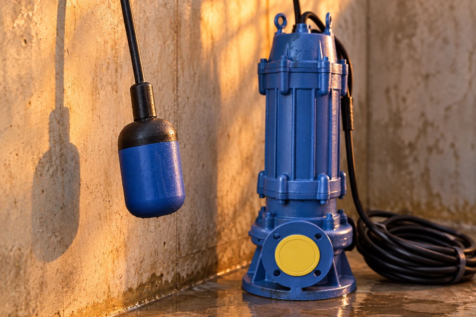
Separate pump requirements from storage requirements
The stop level must respect the selected pump’s documented operating and cooling conditions. A submersible product photograph does not reveal its allowed minimum level or dry-running capability. Request that information for the exact model. Keep the hydraulic inlet condition in view as well: inadequate submergence can create an unstable intake or air entrainment even before the wet well is completely empty.
The start-to-stop volume determines the station’s working storage. That volume influences fill time, runtime and start frequency. Too small a working band can cause frequent cycling; a larger band may affect retention and the available emergency storage. Verify the cycle against the motor and control limits rather than applying a fixed distance between floats.
For model selection, see the Borra WQ submersible sewage pump and obtain the offered installation manual. The sewage pump sizing guide explains why wet-well volume and flow must be assessed together.
Convert level differences into usable volume
Measure the basin geometry and identify where its cross-section changes. For a straight-sided circular portion, volume change is plan area multiplied by level change. For sloping walls or stepped floors, use the actual level-to-volume relationship. Do not calculate a cycle from the outside diameter of the chamber if its internal dimensions or shape differ.
As an illustrative arithmetic example, a circular wet well with an internal diameter of 2 m has an area of approximately 3.14 square metres. A 0.4 m working band therefore stores approximately 1.26 cubic metres within that straight-sided portion. Those dimensions are assumed for the example, not recommended construction values or Borra requirements. The project designer must determine acceptable cycling, storage and operating levels.
Compare the usable volume with measured or designed inflow and installed pumping flow. A station with highly variable inflow should be checked over representative conditions, not only one quiet cycle. Keep the calculation separate from physical adjustment, so an installer cannot unknowingly remove required storage by shortening a tether.
Keep the full movement envelope clear
A tethered float changes position through an arc or movement envelope determined by its design and tether. Position it where it can rise and fall freely without contacting the wall or another device. Check more than the hanging position at an empty basin. The device can move toward piping or cables when the liquid rises or when turbulence pushes it sideways.
Locate floats away from direct inlet impact and heavy local turbulence where the control design permits. Avoid pockets where debris can collect around the device. Keep lifting chains, loose cable and the pump retrieval path clear. The guide-rail installation guide covers the mechanical interfaces that should be reviewed at the same time.
Use the float manufacturer’s mounting and tether instructions. Do not assume an improvised cable tie establishes a stable switching point. A bracket, weight or approved restraint must suit the equipment and environment. Mark and document the installed positions so cleaning or maintenance does not return each device to an arbitrary elevation.
Give the alarm a useful response window
The high-level alarm must provide a meaningful opportunity to act before the station reaches an unacceptable condition. Determine the available storage above the alarm level, credible inflow during the event and the expected response time. A device placed immediately below overflow may signal a problem but leave little time to respond. A device set unnecessarily low can generate nuisance calls during permitted operation.
Consider alarm power, communication and whether the signal is independent enough for the failure cases specified in the design. A local light is useful only if someone can see and respond to it. A remote message is useful only if delivery and escalation are tested. The station’s reliability depends on the whole response arrangement, not the number of floats installed.
For duplex operation, coordinate the lag-pump demand with the alarm and documented reserve. Read duplex sewage pump control before adopting a sequence from another station. Do not assume lag demand and high-level alarm are interchangeable functions.
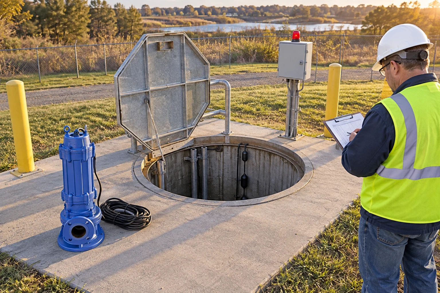
Inspect the layout with a specific checklist
| Function or interface | Check in the field | Evidência a reter |
|---|---|---|
| Stop level | Meets documented pump conditions | Measured elevation and model requirement |
| Start level | Provides the approved working volume | Level-to-volume calculation |
| Lag demand | Produces the intended duplex response | Tested sequence with lead pump operating |
| High alarm | Leaves the approved response reserve | Alarm elevation and response test |
| Float movement | Clear through the full travel | Inspection of walls, inlet and cables |
| Cable support | Stable without strain or tangling | As-built mounting and routing photos |
This qualitative table is an inspection aid, not a wiring diagram. Follow the approved control documentation and device ratings. The official hazardous-energy control regulation explains why maintenance on powered equipment needs effective isolation; do not adjust live wiring as a trial-and-error level test.
Test rising and falling behavior
Use the approved commissioning method to observe both rising and falling levels. Confirm the actual switching point, not only the measured mounting position. Some devices have a difference between actuation and release that must be considered in the control logic. Test the device and the complete controller together, including what the operator sees and hears.
Record pump start, stop, lag response where applicable and high alarm. Verify restoration after a simulated permitted fault and after power returns, using the approved procedure. In a duplex station, confirm whether a failed lead pump transfers duty or merely produces an alarm. Keep fault simulation within the controller’s documented test method.
A successful manual lift of a float does not fully verify the wet-well layout. The device may work by hand yet hang on a wall or cable during actual filling. Combine functional tests with observation of the movement envelope and representative hydraulic conditions. Retest any position changed after cleaning or pump retrieval.
Diagnose frequent starts and missed alarms methodically
If the pump starts too often, compare the installed working volume with the design and inspect for leakage, changing inflow or a drifting signal. Check whether the pump stops at the correct level. Do not simply raise the start float without assessing alarm reserve, retention and the permitted operating range.
If an alarm fails, separate sensor movement, electrical signal, controller response and communication. A clear alarm lamp at the panel does not prove a remote notification arrived. If the float is fouled, find the source of deposits and improve the approved inspection routine. Keep the observed failure and correction in the station log.
For the broader equipment categories, see tipos de bombas de águas residuais before narrowing the selection to this station task.
Perguntas frequentes
How far apart should sewage floats be?
Use the approved elevations and required working volume, together with the device’s movement envelope. A universal distance cannot account for basin area, inflow, motor cycling limits, cooling or emergency storage.
Can one float provide every control and alarm function?
That depends on the documented controller and required failure response. Do not combine functions without design review, especially when an independent high-level alarm is part of the reliability requirement.
Can I lower the stop level to empty the basin?
Only within the approved operating range. Verify pump cooling, intake conditions and control requirements first. Removing more liquid is not automatically desirable if it creates air entrainment or operation below a documented level.
What should be recorded after adjustment?
Record the final elevations, mounting and tether arrangement, switching results, observed cycle and alarm response. Keep the relevant controller logic and pump requirements with the as-built station documentation.
Aprimoramento
This EPA educational session covers wastewater operator calculations, including pump flow and wet-well volume. Use it to understand the quantitative checks in this guide; it does not replace the selected station design or device manual.