
Концевые всасывающие насосы представляют собой одноступенчатые центробежные насосы, в которых жидкость поступает в рабочее колесо в осевом направлении через один всасывающий патрубок и выходит в радиальном направлении через нагнетательный патрубок корпуса. Они широко применяются для чистой или слабозагрязненной воды, систем жизнеобеспечения зданий, орошения, промышленности, систем охлаждения и перекачки. Правильный выбор требует определения рабочей точки, характеристики системы, параметров жидкости, условий всасывания, материалов, уплотнения, электродвигателя, опорной рамы, центровки, средств управления и доступа для технического обслуживания. Термин «концевое всасывание» описывает компоновку, а не универсальный диапазон рабочих характеристик, поэтому окончательную модель необходимо проверять по ее сертифицированной рабочей характеристике.
Настоящее руководство представляет собой предварительную основу для проектирования и закупки, а не замену утвержденному проекту объекта, действующим нормативным требованиям, инструкциям производителя или квалифицированному надзору на площадке. Электротехнические работы, испытания под напряжением, подъемные работы, работы в замкнутых пространствах, работы по обеспечению пожарной безопасности, земляные работы, работа с опасными жидкостями, сточными водами и системами под давлением требуют применения специализированных процедур и компетентного персонала. При устранении неисправностей сохраняйте работоспособность автоматической защиты и доступность системы. Если фактическая жидкость, режим работы, условия на площадке или применимые требования отличаются от принятых допущений, остановите работы и получите пересмотренное техническое заключение.
- Как консольный насос создает расход и напора
- Построить рабочую точку и альтернативные случаи
- Защитите сторону всасывания от кавитации и воздуха
- Выбрать материалы, уплотнение и схему подшипников
- Установите для обеспечения выравнивания и удобства сопровождения
- Комиссия против отклонения от графика и базового плана
- Таблица решений
- Часто задаваемые вопросы
Как консольный насос создает расход и напора
Вращающееся рабочее колесо сообщает жидкости скорость и энергию, в то время как корпус преобразует часть этой скорости в давление. Жидкость обычно поступает через всасывающий патрубок рабочего колеса вдоль оси вала и выходит через улитку или диффузор в сторону нагнетания. Насос не создает фиксированный расход независимо от системы. Его рабочая точка находится на пересечении характеристики насоса и характеристики системы, создаваемой статической высотой подъема и трением. Закрытие напорного клапана смещает точку в сторону меньшего расхода и большего напора; уменьшение сопротивления системы смещает ее в сторону большего расхода. Проверьте КПД, потребляемую мощность, требуемый кавитационный запас, напор при закрытой задвижке и допустимый производителем рабочий диапазон. Работа далеко от проектной зоны может привести к увеличению вибрации, рециркуляции, температуры, нагрузки на уплотнение и энергопотребления.
Построить рабочую точку и альтернативные случаи
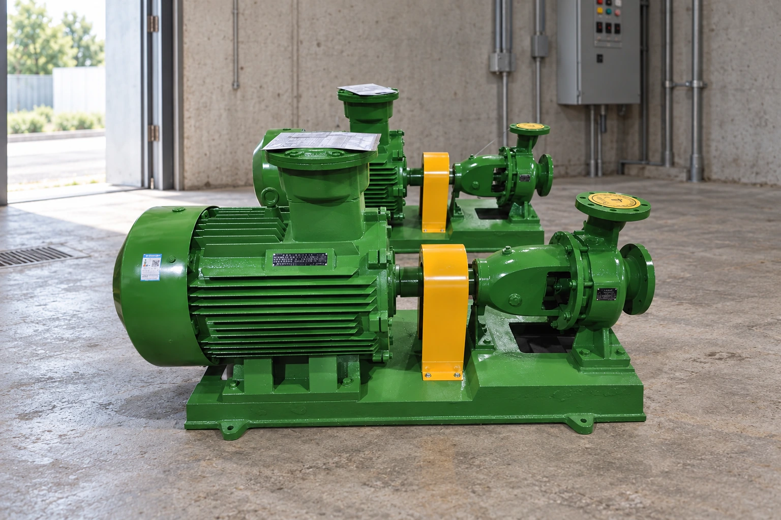
Укажите расчетный режим и полный динамический напор в согласованных единицах измерения. Полный напор включает статическую высоту или разницу давления плюс сопротивление трения в трубах, фитингах, арматуре, сетчатых фильтрах, фильтрах, теплообменниках и другом оборудовании. Разработайте варианты для нормального режима, минимального расхода, максимального расхода и вероятного режима с высоким сопротивлением. Для систем с переменными параметрами учтите уровни в резервуарах, положения клапанов, комбинации параллельно работающих насосов и загрязнение оборудования. Нанесите эти точки на график проектной характеристики. Проверьте потребляемую мощность во всем диапазоне, а не только в расчетной точке, и подтвердите номинальные характеристики двигателя, скорость, напряжение, частоту и способ пуска. Если предлагается использовать частотно-регулируемый привод, запросите характеристики или расчеты для допустимого диапазона скоростей и подтвердите параметры охлаждения двигателя, минимального расхода, расположения датчиков управления, а также поведение системы при обходе (байпасе) или отказе.
Защитите сторону всасывания от кавитации и воздуха
Насос может соответствовать требуемым подаче и напору на бумаге, но при этом работать со сбоями из-за того, что компоновка всасывающей линии обеспечивает недостаточный полезный кавитационный запас (NPSHA). Выполните расчет на основе давления в источнике, уровня жидкости, давления паров, потерь во всасывающей линии и высоты над уровнем моря, используя согласованные абсолютные значения давления. По возможности делайте всасывающий трубопровод коротким и прямым, избегайте высоких точек, где может скапливаться воздух, используйте подходящие переходы и обеспечьте достаточный прямой участок на входе, если это требуется конструкцией насоса и трубопровода. Не опирайте трубопровод на штуцеры насоса и не соединяйте силой несоосные фланцы. Убедитесь, что фильтры, донные клапаны и запорная арматура не создают непредвиденных потерь давления. Под заливом всасывание обычно проще в обслуживании, чем при всасывании с высоты. Стандартные насосы с торцевым всасыванием не являются самовсасывающими по умолчанию; требуется надлежащая система заливки, если корпус и всасывающая линия не могут оставаться заполненными.
Таблица решений по проекту
| Элемент выбора | Доказательства для рассмотрения | Типичная ошибка при пропуске |
|---|---|---|
| Расход и общий напор | Системный расчет и рабочие случаи | Неправильная рабочая точка |
| Условия всасывания | Располагаемый кавитационный запас и компоновка трубопроводов | Кавитация или срыв подачи |
| Свойства жидкостей | Техническое описание и обзор совместимости | Проблемы с коррозией, уплотнением или питанием |
| Напорная характеристика насоса | КПД, мощность, NPSHr, ограничения | Перегрузка или нестабильная работа |
| База и выравнивание | Процедура устройства фундамента и выравнивания | Вибрация и повреждение подшипников |
| Доступ к услуге | Путь демонтажа и план подъема | Чрезмерное время простоя |
Выбрать материалы, уплотнение и схему подшипников
Укажите название жидкости, температуру, плотность, вязкость, содержание твердых частиц, растворенные газы, pH, хлориды и используемые чистящие жидкости. Эти параметры влияют на выбор корпуса, рабочего колеса, вала, крепежа, защитного кольца, прокладки, эластомера и механического уплотнения. Общего описания «нержавеющая сталь» недостаточно, когда важна коррозия; запрашивайте конкретные марки и подтверждение совместимости. План уплотнения и схема промывки должны соответствовать характеристикам давления, температуры, твердых частиц и испарения. Проверьте смазку подшипников, муфту, защитный кожух, опорную плиту, дренажные и вентиляционные соединения, направление вращения и допустимые нагрузки на патрубки. Работа во взрывоопасных или легковоспламеняющихся средах требует проектного анализа классификации оборудования, средств контроля утечек, заземления, вентиляции и требований к зоне установки. Не делайте выводов о пригодности насоса на основе обычной водной характеристики или похожего по внешнему виду насоса.
Установите для обеспечения выравнивания и удобства сопровождения
Установите насос и привод на фундамент или опорную конструкцию, которые соответствуют требованиям поставщика по жесткости и плоскостности. Выровняйте и выполните подливку основания там, где это необходимо, смонтируйте трубопроводы без создания механических напряжений, затем выполните окончательную центровку после монтажа трубопроводов и повторно — в условиях рабочей температуры. Неплотное прилегание лап, напряжения от трубопроводов, плохая центровка муфты и слабые фундаменты могут стать причиной вибрации, а также выхода из строя подшипников или уплотнений, что по своим проявлениям напоминает проблемы с гидравликой. Предусмотрите достаточное пространство для демонтажа электродвигателя, муфты, уплотнения, рабочего колеса или выдвижного узла (back-pull-out). Разместите запорную арматуру и приборы в местах, где технические специалисты смогут безопасно управлять ими и снимать показания. Установите точки измерения давления на входе и выходе, а также рассмотрите возможность мониторинга расхода, вибрации, температуры или мощности в зависимости от критичности оборудования. Компановка, которая обеспечивает экономию места в ущерб техническому обслуживанию, не является полноценным проектом.
Комиссия против отклонения от графика и базового плана
Перед запуском проверьте чистоту, смазку, ограждения, центровку, направление вращения, заполнение, положения клапанов, контрольно-измерительные приборы, электрическую защиту и утвержденную процедуру пуска. Начинайте работу при требуемом режиме нагнетания и избегайте продолжительной работы при закрытой задвижке или ниже допустимого минимального расхода. После стабилизации запишите показатели давления всасывания и нагнетания, расхода, частоты вращения, тока, напряжения, вибрации, температуры подшипников, утечки через уплотнение и уровня шума. Переведите показания манометров в напор насоса, используя правильную точку отсчета и плотность жидкости, затем сравните измеренную точку с характеристикой и расчетом системы. Если характеристики расходятся, проверьте точность приборов, направление вращения, частоту вращения, наличие воздуха, засорение всасывающей линии, положение клапанов, диаметр рабочего колеса, износ и сопротивление системы, прежде чем заменять насос. Сохраните исходные данные для последующего технического обслуживания и энергоаудита.
Акт сравнения и приемки поставщиков
Полное сравнение поставщиков должно использовать один общий лист данных. Разместите наверху расчётные и альтернативные рабочие точки, характеристики жидкости, температуру, содержание твёрдых частиц, высоту над уровнем моря, электропитание, систему управления, монтаж, часы работы, количество, место назначения и требуемую документацию. Унифицируйте различия в объеме поставки перед сравнением цены или эффективности. Запросите сертифицированную кривую или данные по производительности, потребляемую мощность, рабочие пределы, материалы, габариты, массу, патрубки, электродвигатель или привод, контроллер, вспомогательное оборудование, испытания, консервацию, запасные части, инструкции по монтажу и границы гарантии. Фиксируйте каждое отклонение и нерешенное допущение. Во время технического рассмотрения сопоставляйте каждую предложенную характеристику с исходными данными проекта, вместо того чтобы присуждать баллы за функции, которые не требуются для данной рабочей задачи. Во время пусконаладочных работ измеряйте те же переменные, которые использовались при выборе, чтобы полученный при установке результат можно было сравнить с исходным обоснованием. Если условия на объекте отличаются, обновите расчет и получите одобрение ответственного лица перед изменением оборудования или уставок защиты.
Системная интеграция и планирование жизненного цикла
Рассматривайте насос как один из компонентов комплексной гидравлической системы и системы управления. Изучите на одном чертеже источник, водозабор, всасывающий или подводящий патрубок, насос, привод, напорный трубопровод, арматуру, приборы, средства управления, систему электропитания, дренаж, фундамент, пути перемещения при подъеме и приемную систему. Убедитесь в корректности работы в нормальном режиме, при минимальной и максимальной потребности, пуске, останове, перекрытых или закрытых линиях, потере питания, переключении на резерв, реакции на аварийную сигнализацию, очистке и отсечении при техническом обслуживании. Зоны сопряжения часто являются причиной отказов: правильно выбранный насос все равно может работать неэффективно, если фактический подвод отличается от предполагаемого уровня, диаметр трубы меньше проектного, клапан создает непредвиденные потери давления, в контроллере используется датчик не в том месте или при проектировании строительной части был ограничен доступ для обслуживания. Согласуйте зоны ответственности на стыках систем до осуществления закупки. Поставщик насосного оборудования не может утверждать проект здания, колодца, технологического процесса очистки сточных вод, системы пожаротушения, экологических сбросов или электроустановки, если такая ответственность явно не включена в объем поставки и не подтверждена квалифицированной экспертизой.
Планирование жизненного цикла должно начинаться до отгрузки и продолжаться при каждом зафиксированном изменении условий эксплуатации. Определите ожидаемые часы работы, пуски, периоды простоя, условия хранения, маршрут инспекции, способ демонтажа, грузоподъемность, требования к очистке, расходные материалы, критические запасные части, сервисные инструменты и данные, которые операторы будут отслеживать в динамике. Зафиксируйте базовые показатели при приемке и храните их вместе с характеристикой, техническим паспортом, чертежами, настройками контроллера, сертификатами, руководствами и перечнем запасных частей. Будущий специалист должен иметь возможность определить, какая нагрузка была одобрена, что было измерено при пуске и что изменилось. При ухудшении характеристик сопоставьте факты перед заменой оборудования. Расход, давление, уровень, ток, мощность, вибрация, температура, время работы, пуски, аварийные сигналы и состояние жидкости часто позволяют разграничить гидравлические, механические, электрические и технологические причины. Эта запись сокращает количество ненужных замен и способствует принятию более безопасного решения, когда условия эксплуатации перестают соответствовать первоначальному выбору.
Как эта тема связана с оборудованием BORRAPUMP
Это руководство поддерживает предварительное рассмотрение консольные насосы маршрут применения. Он не назначает окончательную модель и не утверждает, что одна стандартная конфигурация подходит для каждого проекта. Отправьте рабочие точки, данные о жидкости, чертеж площадки, электропитание, систему управления, количество, пункт назначения, требуемые согласования и объем инспекции, чтобы предложенное изделие можно было проверить на соответствие реальным условиям эксплуатации.
Связанные технические руководства BORRAPUMP
- насос "инлайн" (циркуляционный насос с патрубками в линию) против консольного насоса
- повысительный насос против центробежного насоса
- работа самовсасывающего центробежного насоса
Авторитетные источники и дальнейшее изучение
Насосные системы Министерства энергетики США; Ресурсы Гидравлического института; Ограждение оборудования по стандартам OSHA. Эти источники обеспечивают общий контекст безопасности, экологии или инженерно-технический контекст. Действующие принятые правила, проектные одобрения и инструкции к оборудованию остаются приоритетными.
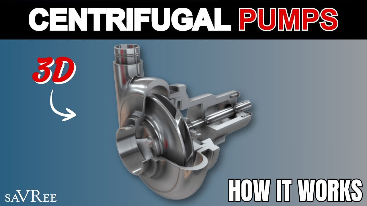
Обучающее видео от saVRee: Как работают центробежные насосы. В нем объясняются основные принципы, и он не заменяет проектно-специфические инструкции.
Часто задаваемые вопросы
Насосы с торцевым всасыванием самовсасывающие?
Стандартные насосы с торцевым всасыванием не являются самовсасывающими автоматически. Уточните конкретную конструкцию и предусмотрите утвержденную систему заливки, где это необходимо.
Что определяет фактический расход насоса с торцевым всасыванием?
Рабочая точка представляет собой пересечение характеристики насоса и характеристики сети с учетом предельных параметров работы насоса.
Могу ли я выбрать из диаметра трубы и мощности?
Нет. Используйте требования к расходу, напору, жидкости, условиям всасывания, характеристике, материалам, приводу и монтажу.
Зачем проверять всю кривую мощности двигателя?
Потребляемая мощность может изменяться при изменении расхода и сопротивления системы. Электродвигатель должен оставаться пригодным во всех возможных рабочих режимах.
Контрольная точка финального проекта
Перед размещением заказа или изменением параметров сверьте утвержденные рабочие характеристики и чертежи с данными поставщика, материалами, размерами, массами, подключениями, приводом, средствами управления, принадлежностями, защитой, объемом испытаний, документацией, запасными частями, методом монтажа, доступом для технического обслуживания и требованиями к месту назначения. Зафиксируйте оставшиеся допущения и назначьте ответственных за их урегулирование. Окончательная принятая информация должна служить основой для монтажа, пусконаладки и последующего технического обслуживания.