
End suction pumps are single-stage centrifugal pumps with liquid entering the impeller axially through one suction connection and leaving radially through the casing discharge. They are widely used for clean or lightly contaminated water, building services, irrigation, industry, cooling, and transfer duties. Correct selection requires a duty point, system curve, liquid data, suction conditions, materials, seal, motor, base, alignment, controls, and maintenance access. The label end suction describes the arrangement, not a universal performance range, so the final model must be checked on its certified curve.
This guide is an early engineering and procurement framework, not a replacement for approved project design, current regulations, manufacturer instructions, or qualified site supervision. Electrical work, energized testing, lifting, confined-space entry, fire-protection work, excavation, hazardous liquids, wastewater, and pressurized systems require task-specific procedures and competent personnel. Preserve automatic protection and system availability while investigating faults. If the actual liquid, duty, site condition, or governing requirement differs from the assumptions, stop and obtain a revised technical review.
- How an end suction pump develops flow and head
- Build the duty point and alternate cases
- Protect the suction side from cavitation and air
- Select materials, seal, and bearing arrangement
- Install for alignment and maintainability
- Commission against the curve and baseline
- Таблица решений
- Часто задаваемые вопросы
How an end suction pump develops flow and head
The rotating impeller adds velocity and energy to the liquid, while the casing converts part of that velocity into pressure. Liquid normally enters through the impeller eye along the shaft axis and exits through the volute or diffuser toward the discharge. The pump does not create a fixed flow independently of the system. Its operating point is where the pump curve intersects the system curve created by static head and friction. Closing a discharge valve moves the point toward lower flow and higher head; reducing system resistance moves it toward higher flow. Review efficiency, absorbed power, net positive suction head required, shutoff head, and the manufacturer's permitted operating range. Running far from the intended region can increase vibration, recirculation, temperature, seal stress, and energy use.
Build the duty point and alternate cases
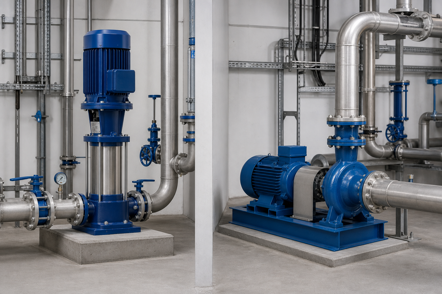
State design flow and total dynamic head in consistent units. Total head includes static elevation or pressure difference plus friction through pipe, fittings, valves, strainers, filters, heat exchangers, and other equipment. Develop normal, minimum-flow, maximum-flow, and credible high-resistance cases. For variable systems, include tank levels, valve positions, parallel-pump combinations, and fouled equipment. Plot those points against the proposed curve. Check absorbed power across the range rather than only at the design point, and confirm the motor rating, speed, voltage, frequency, and starting method. If a variable-frequency drive is proposed, request curves or calculations over the allowed speed range and confirm motor cooling, minimum flow, control sensor location, and bypass or failure behavior.
Protect the suction side from cavitation and air
A pump can meet flow and head on paper yet fail because the suction arrangement provides insufficient net positive suction head available. Calculate from source pressure, liquid level, vapor pressure, suction losses, and site elevation using consistent absolute-pressure terms. Keep the suction route short and direct where practical, avoid high points that trap air, use appropriate reducers, and provide enough straight approach if required by the pump and piping design. Do not support piping from the nozzles or force misaligned flanges together. Confirm that strainers, foot valves, and isolation valves do not add unexpected loss. Flooded suction is generally easier to manage than suction lift. Standard end suction pumps are not automatically self-priming; a proper priming arrangement is required when the casing and suction line cannot remain filled.
Таблица решений по проекту
| Selection item | Evidence to review | Common failure if omitted |
|---|---|---|
| Flow and total head | System calculation and operating cases | Wrong operating point |
| Suction conditions | NPSH available and piping layout | Cavitation or loss of prime |
| Liquid properties | Data sheet and compatibility review | Corrosion, seal or power problems |
| Pump curve | Efficiency, power, NPSHr, limits | Overload or unstable operation |
| Base and alignment | Foundation and alignment procedure | Vibration and bearing damage |
| Service access | Removal path and lifting plan | Excessive downtime |
Select materials, seal, and bearing arrangement
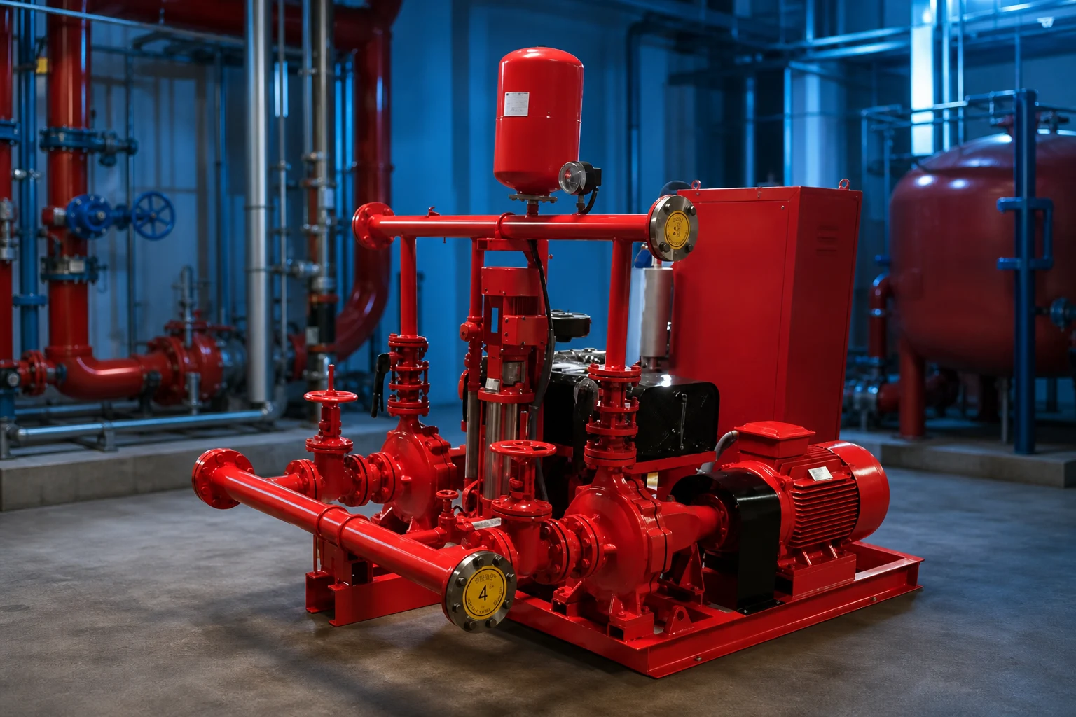
Provide the liquid name, temperature, density, viscosity, solids, dissolved gases, pH, chlorides, and any cleaning fluids. These inputs influence casing, impeller, shaft, fastener, wear-ring, gasket, elastomer, and mechanical-seal choices. A generic stainless description is not enough when corrosion matters; ask for actual grades and compatibility evidence. The seal plan and flush arrangement must suit pressure, temperature, solids, and vapor characteristics. Review bearing lubrication, coupling, guard, baseplate, drain and vent connections, rotation, and allowable nozzle loads. Hazardous or flammable service requires a project-specific review of equipment classification, leakage controls, grounding, ventilation, and area requirements. Do not infer suitability from an ordinary water curve or a similar-looking pump.
Install for alignment and maintainability
Place the pump and driver on a foundation or support that meets the supplier's stiffness and flatness requirements. Level and grout the base where required, complete piping without imposing strain, then perform final alignment after piping and again under relevant temperature conditions. Soft foot, pipe strain, poor coupling alignment, and weak foundations can produce vibration and bearing or seal failures that resemble hydraulic problems. Provide space to remove the motor, coupling, seal, impeller, or back-pull-out assembly. Locate valves and instruments where technicians can operate and read them safely. Install suction and discharge pressure measurement points, and consider flow, vibration, temperature, or power monitoring according to criticality. A compact layout that blocks maintenance is not a complete design.
Commission against the curve and baseline
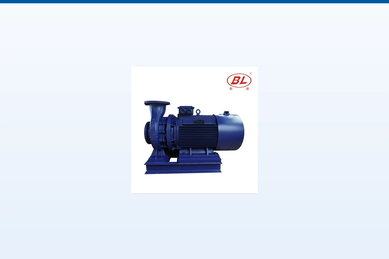
Before startup, verify cleanliness, lubrication, guards, alignment, rotation, priming, valve positions, instruments, electrical protection, and the approved startup procedure. Start with the required discharge condition and avoid extended operation at shutoff or below the permitted minimum flow. Record suction and discharge pressures, flow, speed, current, voltage, vibration, bearing temperature, seal leakage, and noise after stabilization. Convert gauge readings to pump head using the correct reference and liquid density, then compare the measured point with the curve and system calculation. If performance differs, check instrument accuracy, rotation, speed, air, suction blockage, valve position, impeller diameter, wear, and system resistance before changing the pump. Keep the baseline for later maintenance and energy reviews.
Supplier comparison and acceptance record
A complete supplier comparison should use one common data sheet. Put the design and alternate duty points, liquid, temperature, solids, site elevation, power, controls, installation, operating hours, quantity, destination, and required documents at the top. Normalize differences in scope before comparing price or efficiency. Request a certified curve or capacity data, absorbed power, operating limits, materials, dimensions, weight, connections, motor or driver, controller, accessories, tests, preservation, spare parts, installation instructions, and warranty boundary. Record every deviation and unresolved assumption. During technical review, trace each offered feature back to a project input instead of awarding points for features that the duty does not need. During commissioning, measure the same variables used for selection so the installed result can be compared with the original basis. If field conditions differ, update the calculation and obtain responsible approval before changing equipment or protection settings.
System integration and lifecycle planning
Treat the pump as one component of a complete hydraulic and control system. Review the source, intake, suction or inlet arrangement, pump, driver, discharge piping, valves, instruments, controls, power, drainage, foundation, lifting route, and receiving system on the same drawing. Confirm normal operation, minimum and maximum demand, startup, shutdown, blocked or closed paths, loss of power, standby changeover, alarm response, cleaning, and maintenance isolation. Interfaces create many failures: a correctly selected pump can still underperform because the available supply differs from the assumed level, a pipe is smaller than scheduled, a valve has an unexpected pressure loss, a controller uses the wrong sensor location, or maintenance access was removed during civil design. Resolve interface ownership before purchase. The pump vendor cannot approve the building, well, wastewater process, fire-protection system, environmental discharge, or electrical installation unless that responsibility is explicitly included and supported by qualified review.
Lifecycle planning should begin before shipment and continue through every documented operating change. Identify the expected operating hours, starts, standby periods, storage conditions, inspection route, removal method, lifting capacity, cleaning requirement, consumables, critical spares, service tools, and data that operators will trend. Establish baseline readings during acceptance and keep them with the curve, data sheet, drawings, controller settings, certificates, manuals, and parts list. A future technician should be able to tell what duty was approved, what was measured at startup, and what changed. When performance deteriorates, compare evidence before replacing equipment. Flow, pressure, level, current, power, vibration, temperature, runtime, starts, alarms, and liquid condition often separate hydraulic, mechanical, electrical, and process causes. This record reduces unnecessary replacement and supports a safer decision when operating conditions no longer match the original selection.
How this topic connects to BORRAPUMP equipment
This guide supports early review of the end suction pumps application route. It does not assign a final model or claim that one standard configuration fits every project. Send the duty points, liquid data, site drawing, power supply, controls, quantity, destination, required approvals, and inspection scope so the proposed product can be checked against the real service.
Связанные технические руководства BORRAPUMP
- inline pump vs end suction pump
- booster pump vs centrifugal pump
- self-priming centrifugal pump working
Authoritative sources and further learning
U.S. Department of Energy pump systems; Hydraulic Institute resources; OSHA machine guarding. These sources provide general safety, environmental, or engineering context. The current adopted rules, project approvals, and equipment instructions remain controlling.

Educational video by saVRee: How Centrifugal Pumps Work. It explains background principles and does not replace project-specific instructions.
Часто задаваемые вопросы
Are end suction pumps self-priming?
Standard end suction pumps are not automatically self-priming. Confirm the specific design and provide an approved priming arrangement where required.
What defines the actual flow of an end suction pump?
The operating point is the intersection of the pump curve and system curve, subject to the pump operating limits.
Can I select from pipe diameter and horsepower?
No. Use flow, head, liquid, suction conditions, curve, materials, driver, and installation requirements.
Why check the whole curve for motor power?
The absorbed power can change as flow and system resistance change. The motor must remain suitable across credible operating points.
Final project checkpoint
Before order placement or field change, reconcile the approved duty and drawings with the supplier data, materials, dimensions, weights, connections, driver, controls, accessories, protection, test scope, documentation, spare parts, installation method, maintenance access, and destination requirements. Record remaining assumptions and assign responsibility for closing them. The final accepted information should be the same basis used for installation, commissioning, and future maintenance.