
Centrifugal pump shaft keyway inspection should examine the complete keyed connection: the key, the slot in the shaft and the mating slot in the impeller hub. Replacing a visibly damaged key without measuring the surrounding parts can leave the original looseness, distortion or cracking in place. Identify the actual assembly design, preserve the removed parts and compare measurements with the correct drawing before authorizing reassembly. There is no single acceptable keyway clearance for every centrifugal pump.
This guide focuses on inspection and repair decisions for a keyed impeller connection. It does not assume that every pump uses a key, that the key retains the impeller axially, or that an oversized key is an approved repair.
Confirm which connection you are inspecting
Start with the model, serial number, sectional drawing and parts list. Some impellers use different attachment arrangements, so do not order a key from an exterior product photograph. Identify the shaft keyseat, hub keyway, key style and any separate nut, washer, sleeve or other retention component. Record their order before removal under the approved dismantling procedure.
Keep the impeller key separate from a driver-coupling key. They may differ in dimensions, material, function and assembly requirements even on the same pump. Label each removed part against its location. A mixed tray of apparently similar keys can turn a straightforward repair into an uncertain parts-identification exercise.
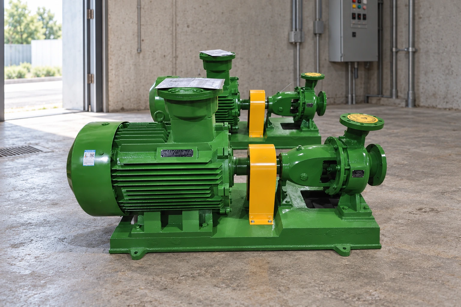
เดอะ IS clean-water centrifugal pump range is a useful starting point for a product inquiry. Its external images establish a product family, not an internal key size or material. Supply the actual unit’s identification and component information when requesting a replacement.
Make removal safe and preserve the contact marks
Isolate the equipment and connected liquid sources according to the site’s procedure, verify pressure removal and account for automatic starting. Use the approved support and lifting arrangements for the rotating assembly. Do not treat the keyway as a convenient attachment point for an improvised puller, wedge or lifting hook.
Before cleaning, photograph the key in its installed orientation where access allows. Note which side faced the driver, whether the key moved during removal and whether burrs or loose debris were present. Keep broken fragments together and avoid grinding a damaged slot before documenting it. The original contact pattern may be useful to the person assessing the connection.
If dismantling requires unusual force, stop and investigate the prescribed method rather than assuming that harder hammering will solve the problem. A seized hub, interference arrangement or hidden retaining component can require a different approach. Damage introduced during removal should be recorded separately from damage that existed in service.
Understand what the key is meant to do
A key provides a mechanical path for torque between the shaft and hub in the specified design. Its effectiveness depends on the connection geometry and material, rather than merely whether it can be inserted into the slot. The NPTEL machine-design lesson on keys explains different key arrangements and the associated torque-transfer concepts.
Do not assume that the key alone controls all axial movement or that the top face must be tightly trapped. Those details depend on the particular design. Check the specified width, depth, engagement, end form and surrounding shaft-to-hub fit. A connection can contain a new key yet still be wrong because the hub does not seat at its intended axial position.
For a maintenance inspection, the immediate task is comparison with approved dimensions. Recalculating a stronger key from nominal motor power does not establish that the shaft, hub and retention arrangement can accept a modified load path. Any redesign needs an engineering assessment beyond a general replacement checklist.
Inspect the three mating components separately
Examine the key for deformed edges, displaced material, unusual polishing, corrosion and fracture. Record where each feature occurs rather than simply describing the part as worn. A key that appears untouched on one face and heavily marked on another needs to be considered alongside the shaft and hub condition.
Inspect the shaft slot for width variation, damaged ends, burrs, pits and suspicious linear indications. Check the adjacent shaft seat and shoulder because a damaged seating surface can affect the assembly independently of the key. Avoid assuming that a locally raised burr represents the original slot width; identify surface damage before deciding how dimensions should be measured.
Inspect the hub slot and bore as well. Look for contact concentrated near one end, damaged corners and evidence of relative movement. A good-looking shaft keyseat does not clear a worn impeller hub. Likewise, changing the impeller alone may leave a damaged shaft connection that will mark the new part during service.
| Component or observation | Record before deciding | Useful next question |
|---|---|---|
| Key with crushed or rolled edge | Location, orientation and matching marks | Do the mating slots meet the drawing? |
| Shaft slot wider in one area | Measurements at identified axial positions | Is the variation wear, damage or specified geometry? |
| Hub bore with rubbing marks | Bore condition and seating location | Is the shaft-to-hub fit acceptable independently of the key? |
| Pitting or a linear indication | Photographs and inspection location | Is qualified further examination required? |
| New key prevents full seating | Actual key dimensions and assembly sequence | Is the key form or another retained component incorrect? |
Measure against a traceable drawing
Record the drawing number, revision and component identification on the inspection sheet. Use an appropriate calibrated instrument and a measurement plan that covers relevant positions along the slot. Include units and identify the measurement direction. One unlabelled number called “keyway size” is insufficient to compare width, depth and engagement.
Measure the replacement key separately before assembly. A package description or nominal stock size does not prove that the supplied piece meets the required finished dimensions. Preserve the material identification, especially when corrosion resistance or mechanical properties matter. Do not substitute a softer or harder material on the assumption that either is automatically safer.
A practical report records measured values, specified limits and the resulting disposition in separate columns. Where the drawing is missing, leave acceptance open and request the required data. Reporting “fits by hand” may describe an observation, but it cannot replace dimensional acceptance where the design calls for a controlled fit.
Treat cracks and corrosion as a separate assessment
A suspicious indication at a slot end should not be dismissed because a new key fits. Ask a qualified inspector to determine whether additional examination is needed and which technique suits the material and geometry. Surface accessibility, preparation and defect orientation can affect what an examination reveals.
เดอะ EPRI Vertical Pump Maintenance Guide includes examples involving keyway pitting and crack initiation in particular vertical-pump coupling applications. Those examples illustrate the value of preserving localized evidence; they are not acceptance limits or proof of the failure mechanism in a different centrifugal pump.
If the review finds a crack, define the component disposition before machining or reassembly. Repair, replacement and further examination should be selected using the actual part and service conditions. Do not conceal an unresolved indication by polishing the slot until it is less visible or by fitting a key that bridges the affected area.
Separate keyway fit from shaft runout and balance
Keyway inspection answers a different question from checking whether a shaft runs true. Use the pump shaft runout guide when the measurement concerns geometric rotation. Record its results alongside the keyway inspection, but avoid using one satisfactory reading to waive another relevant check.
Similarly, a balanced impeller can still have a damaged hub interface. The impeller balancing guide covers the balancing question, including the need to identify the assembly condition used for the assessment. If a repair changes the rotating component or its key arrangement, ask whether the approved balancing instructions require further work.
เดอะ shaft sleeve inspection guide addresses another adjacent interface. Its dimensions and sealing condition should not be confused with the key’s torque-transmission function. A clear work order gives each component its own inspection result and connects them through the assembly drawing.
Approve the repair scope before modifying the slot
Do not make an oversized key, add shim material or recut the slot solely because it removes noticeable movement. Such changes can affect engagement, remaining section, stress concentration and interchangeability. They require an approved repair drawing or replacement decision covering all mating parts.
Ask the repair provider to identify which component is being restored, which dimensions will be inspected and who approves the finished connection. Clarify whether the quote includes the impeller bore, shaft seat, keyway examination, material records and any required balancing. A proposal that says only “supply new key” may not address the observed damage.
Before reassembly, confirm the key orientation, seating and axial retention against the manufacturer instructions. Record the fitted components and any approved deviations. If the hub will not seat without unusual force, reopen the dimensional review instead of filing the key until assembly becomes possible. Easy assembly is useful only when the resulting geometry is correct.
Record the result for the next maintenance event
The final inspection sheet should include component photographs, measured dimensions, drawing references, replacement identification and acceptance signatures. Keep removed parts available until the failure investigation is closed. If several similar pumps operate at the site, tie the records to the individual serial number rather than only the station name.
For a replacement inquiry, provide the shaft and impeller identifiers together. State whether the request concerns a new key, a damaged shaft, a worn hub or an unresolved assembly issue. Supplying that distinction early helps a manufacturer ask the right questions and reduces the risk of buying a part that cannot correct the problem.
Educational background: torque and torsion
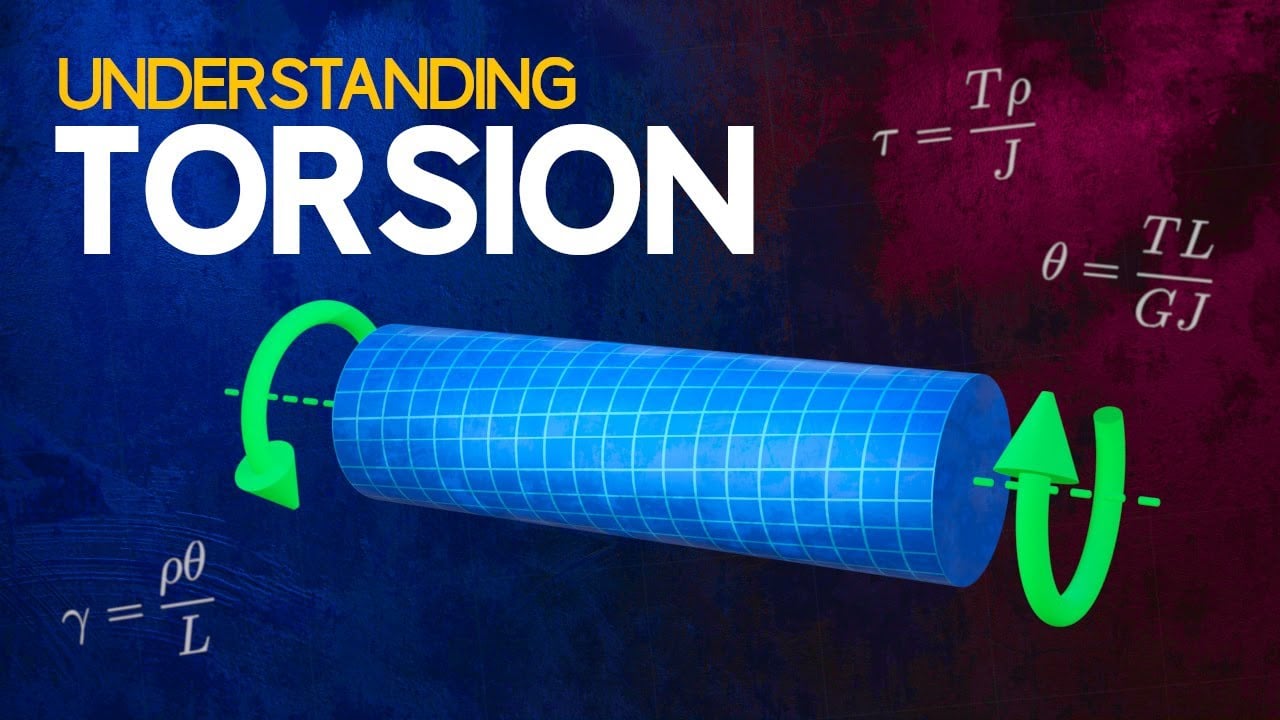
The Efficient Engineer’s Understanding Torsion video explains torque and twisting stresses in a shaft. It supports understanding the load path discussed here, but it does not provide pump keyway dimensions or authorize a repair. Use the actual assembly drawing and engineering decision for acceptance.
คำถามที่มักถูกถาม
Can I replace only the impeller key?
Only after inspecting the mating shaft slot, hub slot and relevant seating surfaces. A new key cannot restore a worn or damaged mating component by itself.
Should I file a key until the impeller slides on?
Do not use trial filing as an acceptance method. Identify the specified dimensions and assembly arrangement, measure the parts and resolve the cause of interference through the approved instructions.
Is there a standard clearance that applies to every pump?
No single clearance can be assigned to every keyed pump connection. Use the component drawing, key form, material and manufacturer requirements for that actual assembly.
Does a key prevent the impeller moving axially?
That depends on the design. Many assemblies use separate retention features; identify them from the sectional drawing rather than assuming the key controls axial position.
Can a balanced impeller still have a bad keyway?
Yes. Balance and the condition of the torque-transfer interface are different checks. A satisfactory balance result does not establish that the shaft, key and hub meet their dimensional requirements.